
The Idea - What Is A State Machine?
Prerequisites:
Make sure you completed The Maze level. I also use KV diagrams later on, so you might check out this guide before: KV diagrams
Imagine you have to build a circuit to control some kind of device. You don't have a full computer - only basic gates, and need to come up with a solution, so that your device behave the way you want it to.
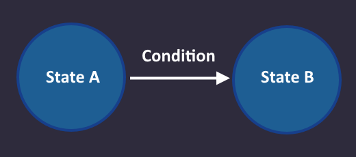
The idea is, that we go over all possible things that our device can do step-by-step. We draw a circle for each of those steps and call it a state. Usually every possible output that our device can have has at least one state. We then connect this circles by arrows that have a certain condition assigned to it (called transitions). These conditions are usually a speficic configuration of input signals (What shall the device do when certain inputs arrive).
This means something like that:
We go from state A to state B, when the condition on the arrow from A to B is met.
By doing so, we can construct a picture where the complete behaviour is visible for us and we can understand it easily (= state machine). The cool thing is: There is a completely deterministic way to convert this pictures to circuits by following a few steps, and your device will do exactly what you specified in the picture. It is so straight forward, that you can technically write a program that converts state machines to circuits.
If thats to easy for you, you can then go and optimize your state machine to get an even better result with super few gates (thats the fun part).
Small spoiler:
What do you think how many gates you need to solve The Maze? 20? 10? 6? Nope - even fewer. You can scroll all the way to the end to see the solution, but you get the most out of it, when you also understand why that solution works.
Step 1: Draw A Simple State Machine

We have a perfect example for a level which we can solve using a state machine: The Maze
Looking in the level description, we find a hint where the exact behaviour is described
1: Step forward 2: Turn left 3: Turn right as long as there is a wall ahead 4: Press use after each turn (in case the exit is ahead) 5: Repeat
This is the behaviour we want to implement, but we don't want to use a computer - only basic gates.
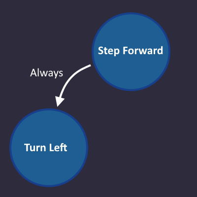
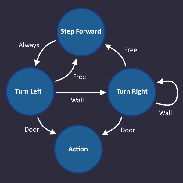
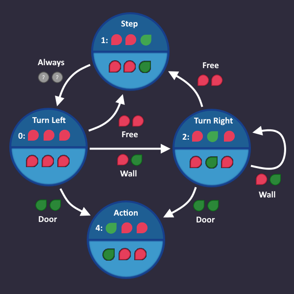
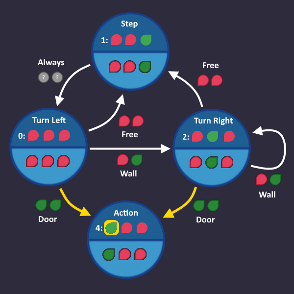
We start with line 1: Step forward
simple enough.
Lets go on with line 2: Turn left
We always do that after we take a step forward, so 'always' is our condition, that we write on the transition arrow. There is no right and wrong, it only has to make sense for us as humans.
Makes sense?
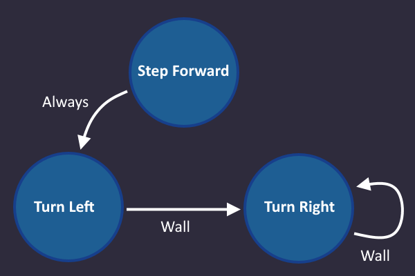
Here comes line 3: Turn right as long as there is a wall ahead
Now we have our first 'real' condition. As soon as our input tells us "There is a wall ahead", we go from Turn left to Turn right, and stay there as long as our input sees a wall.
Note: In each tick the machine has to use one of the arrows, based on its input values.
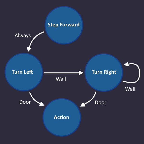
Lets continue: Press use after each turn (in case the exit is ahead)
Basically what this means is: If you see a door after you turned, then use the action command
So we add an Action state that we enter, when we see a door, after we turned
Since the door is the end, we don't need any arrows going out from there.
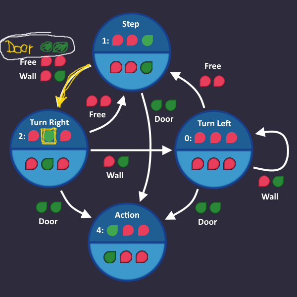
Time for the last line: Repeat
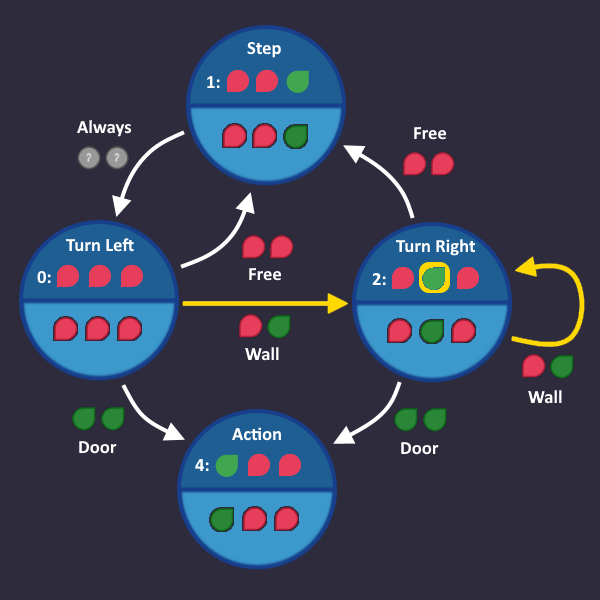
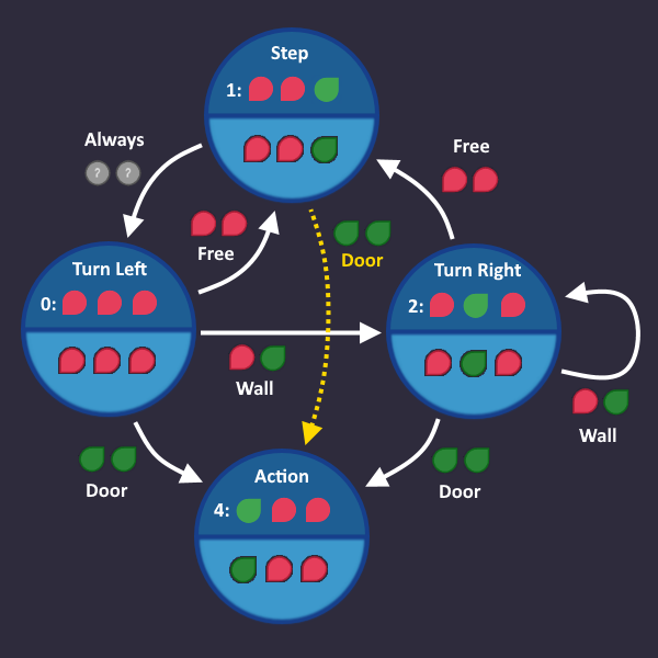
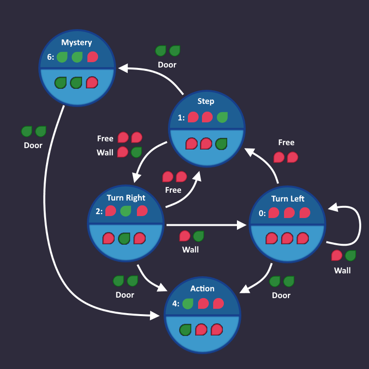
It means, we start over with the first step, if we see a free space. Let's add that:
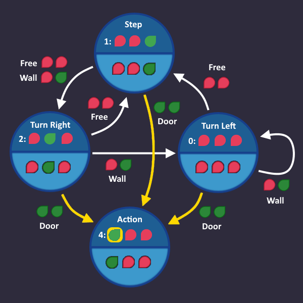
And that's it! Thats all we need. In each tick, we check the roboters inputs and take the transition that matches that condition. Now we have to convert that into a circuit.
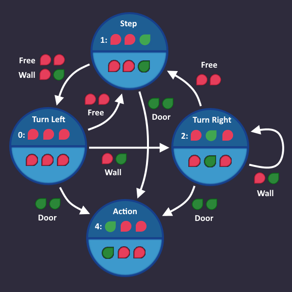
Step 2: Add Outputs


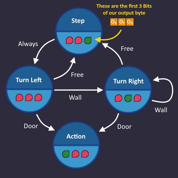
Since we now know which states there are, we also know which output signals we have to send during a particular state.
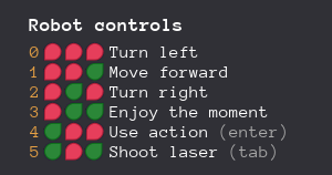
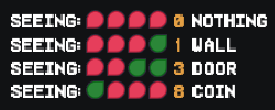
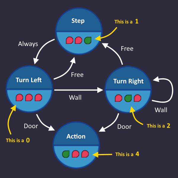
Lets take a look at all the output signals, that the robot understands
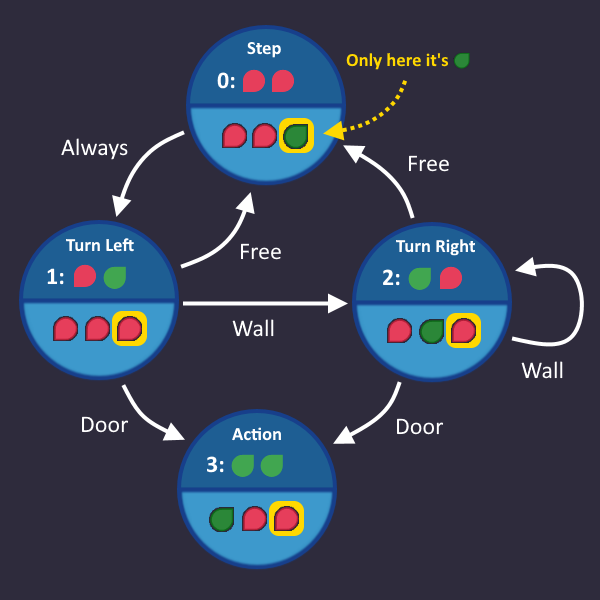
In each state, we send one of these signals to the output. E.g. when we are in state Turn Right, then we send the corresponding signal to the output, which is .
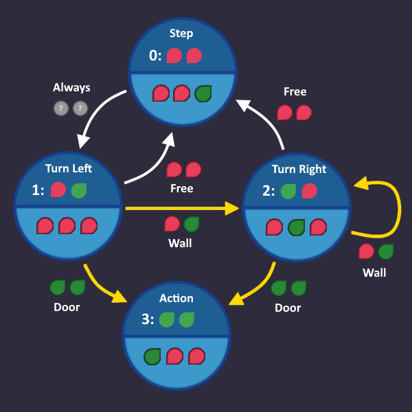
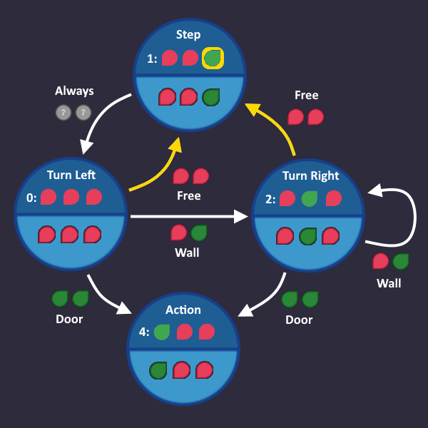
We can add that information to our graph for each state:
Step 3: Number The States
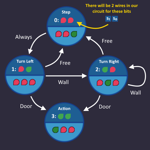
Each state needs a unique id (bit pattern), so that we can identify in which state we are currently in. This id is completely arbitrary - we can choose whatever we want, the only thing that matters is, that it is unique for each state.
The easiest (but not necessary the smartest) way to do that is to simply assign a number to each state. By doing so, each state can be referenced using that number.
Lets do it and add that information to our graph: we have 4 states, so we count from 0 to 3 - and we need 2 bits to represent every number.
What does this mean for our circuit?
Somewhere in our circuit there are 2 wires that represent our state number. We can access these wires at any time if we want to know which state is currently active.
HOLD ON!
That also means that we can already start building things! We can access the state wires, and we already plugged in our output signals, that we want to send in a particular state...
So assuming that the state wires are already there - we can build the part, that sends output signals!
Step 4: Build The Output Circuit


 StateName
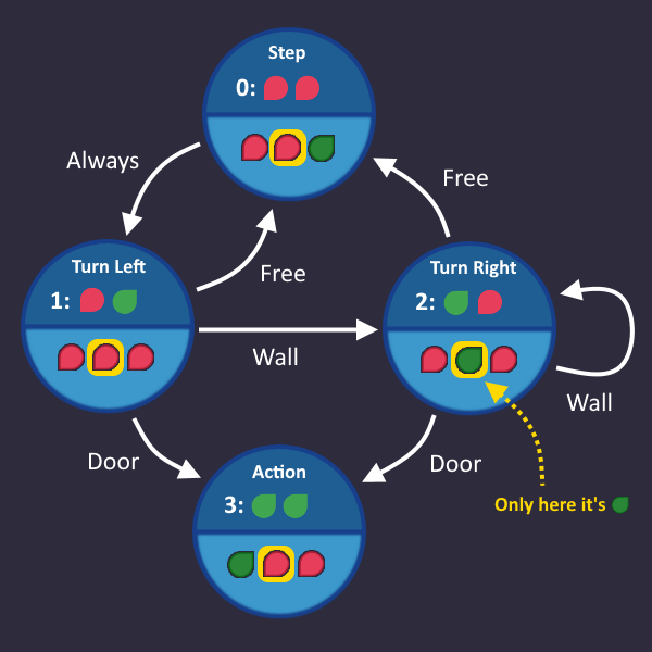 StateName
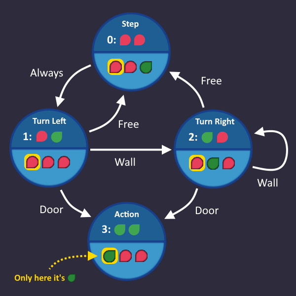 StateName
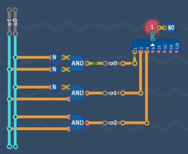
Okay, we know that there are 2 wires that provide the number of a state. And if we know the state number, we can determine which of the output bits has to be .
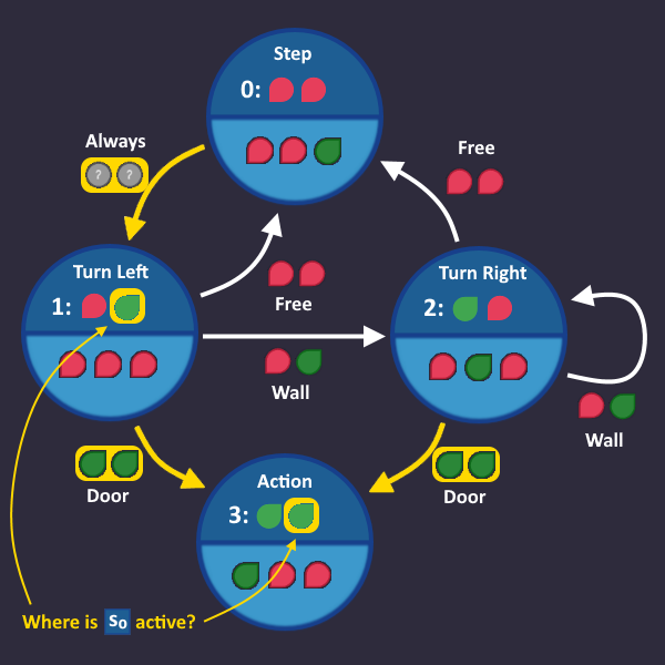
So lets start with and see in which state it needs to be . Look at the graph and write down all state numbers in which this bit is .
It is in only one state, so lets write that down:
Step forward
It's only one state here, but there could be more in theory - leading to a bigger table.
Lets continue with :
Writing down all states where it is
Turn Right
And finally for :
Again, there is only one state where the bit is
Action
We are almost done - we just have to build our tables now. For each state that we have written down, AND all signals together. If you have more than one state in a table, then OR these ANDs (for each state) together, to get the final signal. (In short: AND the columns for each row, and OR all rows)
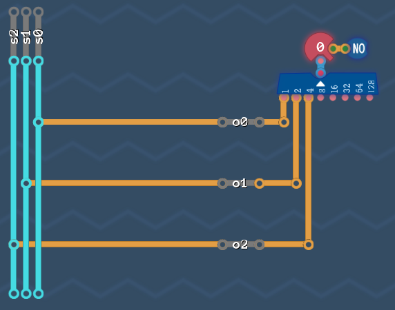
Our circuit for all 3 bits looks like this:
Okay great - we build the output. But we need the s-Signals for that... so how do we do that?
Step 5: Translate The Transition Conditions

 Means
Means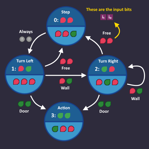
The signals represent our state. So we have to make sure, that the signal on these wires change, whenever we take a transition from one state to another (so they represent the new state).
That we have to translate the words, that are written on our arrows into bits.
All these words represent some kind of input value, that the roboter sees. So lets take a look at all the things that we can find in the maze:
How do these inputs correspond to the words we wrote on our arrows?
Door and Wall are obvious. But what does 'Free' mean?
Well, it either Nothing or Coin, because we can walk over a coin as if its nothing. But that also that we only have to focus on the first two input bits, because they are both for Nothing and Coin, but different for any other input.
That in the end we have the following conditions, based on the first two input bits :
Free Wall Door Always (we don't care about the value of the input)
Alright, lets put that into our graph!
Note: There can be multiple conditions on a single arrow (e.g. Door + Wall). You can write that in a little table as we did above (and later you OR all the conditions together)
Step 6: Build The Transition Circuit
 Origin StateCondition
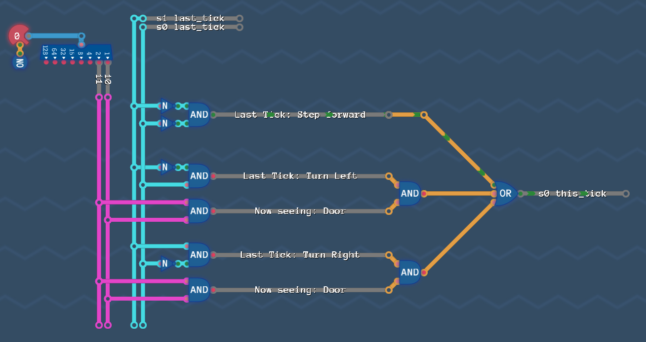
 Origin StateCondition
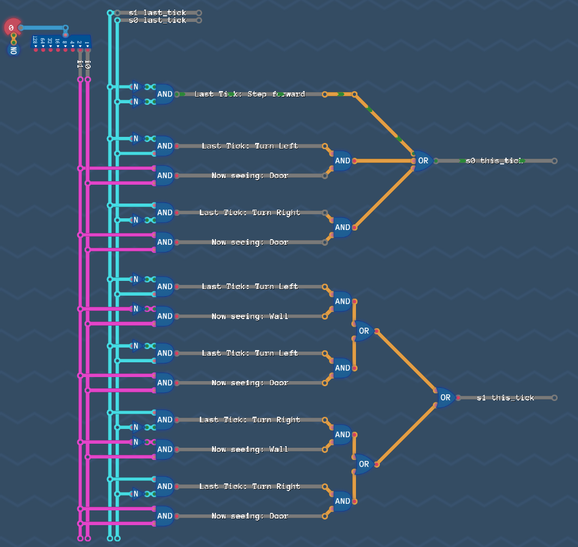
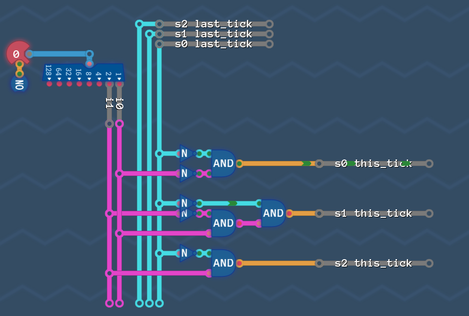
We now have all the information that we need to build the circuit for our wires.
We begin with the wire for
Here is what we do:
We look at all the states where is
We look at all the arrows that go into these states (because these arrows are the reason, that our bit is now )
For all these arrows, we write down from which state they are comming from, and which condition the arrow has
So lets see:
We have to look at all states where is and all arrows that lead to this state
Now lets write down all these arrows together with the state where they start
Step Forward Always Turn Left Door Turn Right Door
Lets interpret what we just wrote down.
The first row says:
"If we were in state 'Step' last tick, then whatever is at the input - we will turn the s0 bit on in this tick"
The second row says:
"If we were in state 'Turn Left' last tick, and our input now sees a door, then we turn the s0 bit on"
The third row says:
"If we were in state 'Turn Right' last tick, and our input now sees a door, then we turn the s0 bit on"
So the bit turns if any one of those three statements is true, so we simply OR them together. Like before: AND all columns and OR all rows.
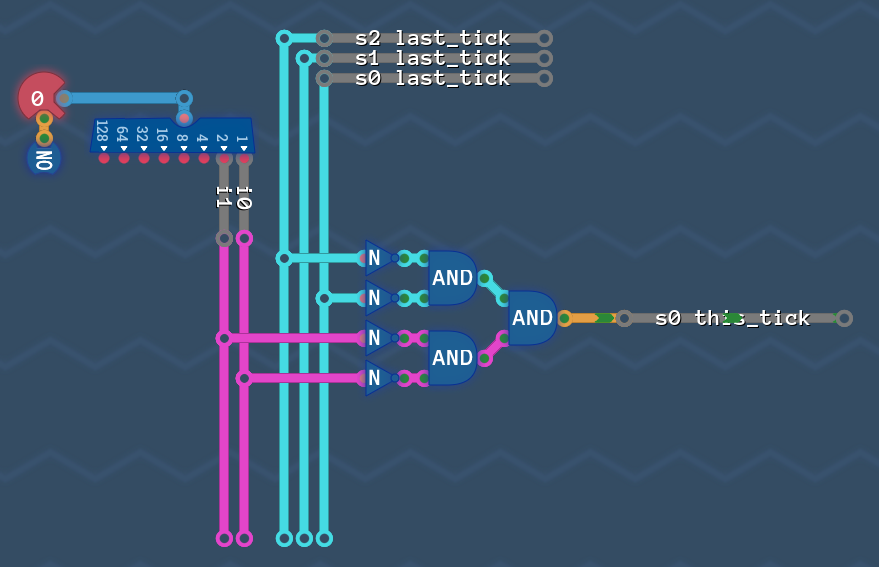
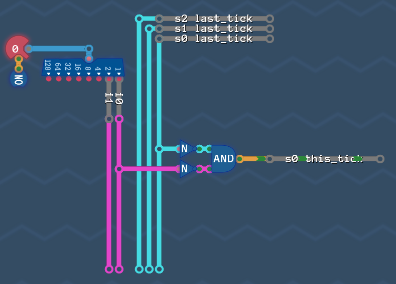
So lets build it! (We once again just have to implement the table from above).
As a careful observer you may have seen that you can reuse the AND gate that detects the door - but lets continue and optimize later.
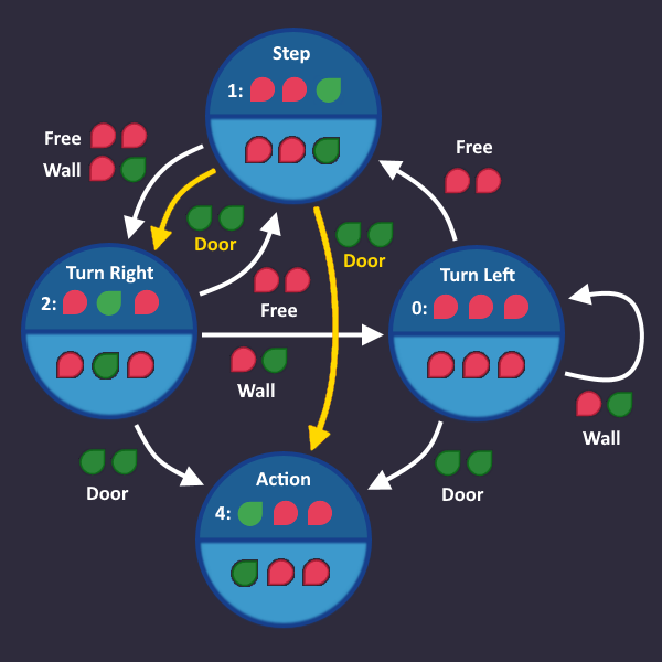
Alright, is done - lets do the same with
Same as before: Collect all arrows, that lead to a s1-bit
The relevant arrows are the yellow ones:
Lets write down the table for it
Turn Left Wall Turn Left Door Turn Right Wall Turn Right Door
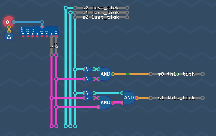
We already build some of those arrows, but lets optimize later and expand our circuit:
All the rows in our table have ANDs, that are ORd together.
We are almost done! We just need to put it all together.
Step 7: Put Everything Together
Now there are two more things left to do. The fist one is kinda obvious:
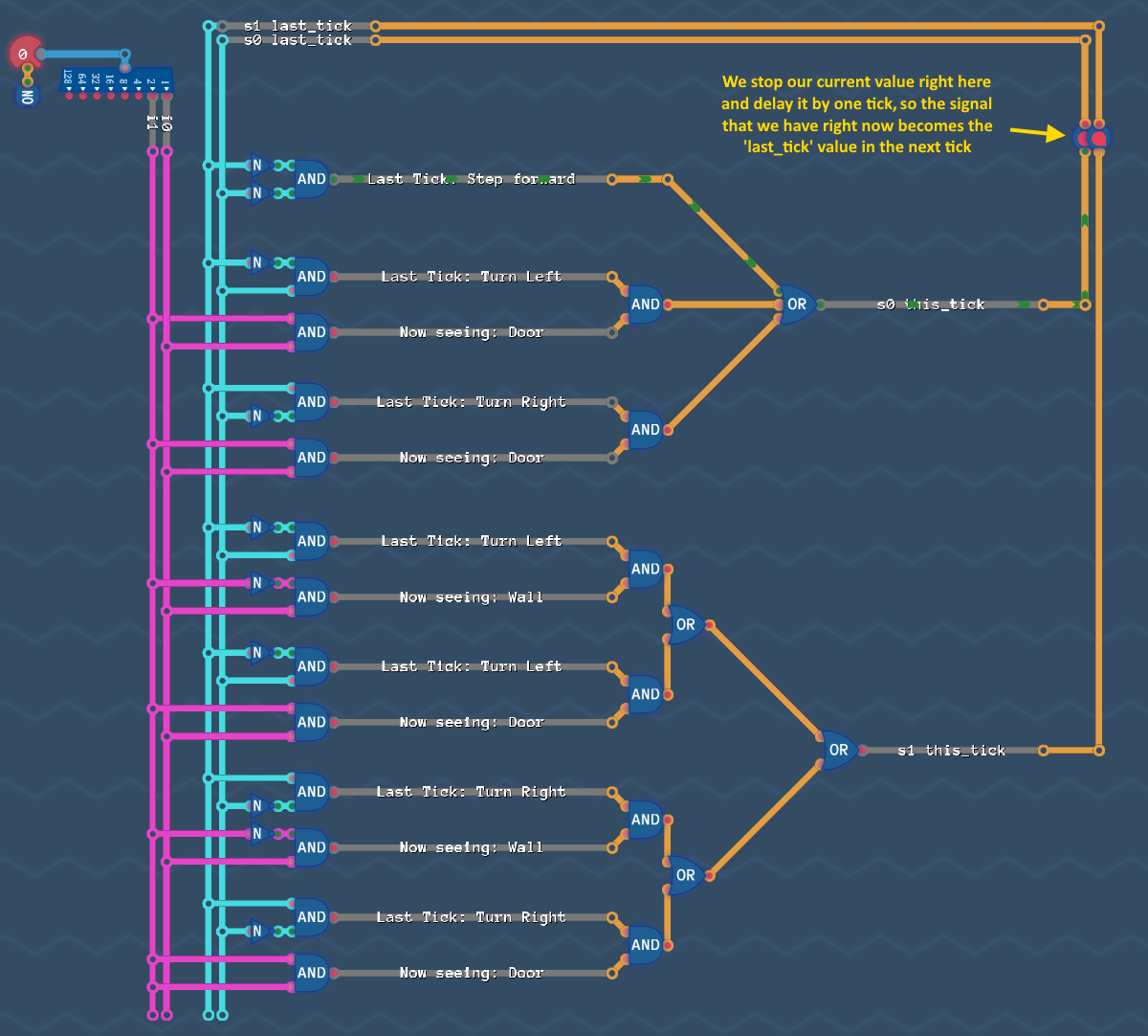
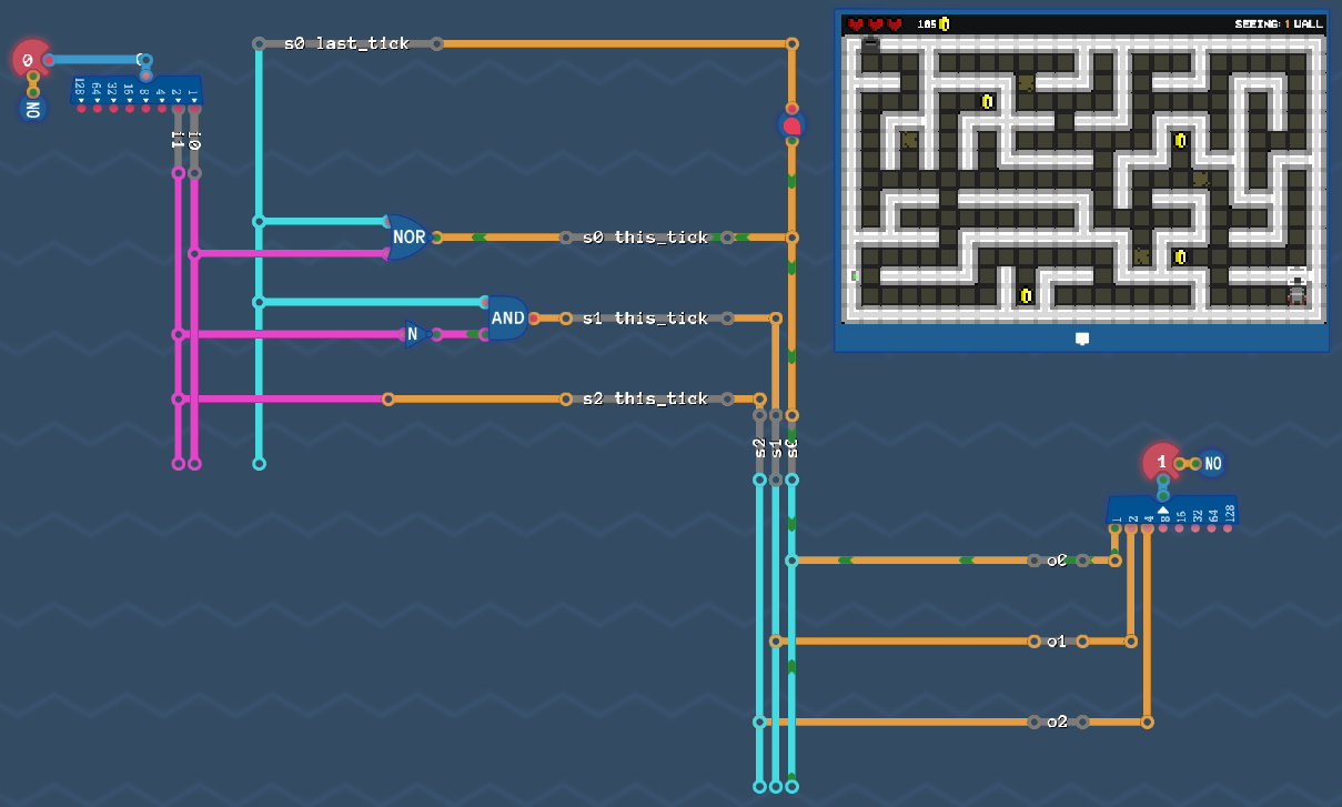
In the last step we produced our state bits based on the value they had in the tick before. So lets make sure, that the signal we produced is available on these wires in the next tick for us to calculate again. We simply have to add a delay line like this:
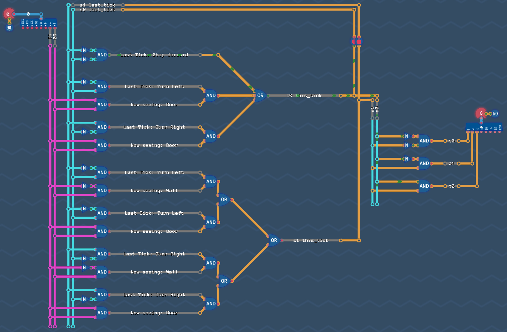
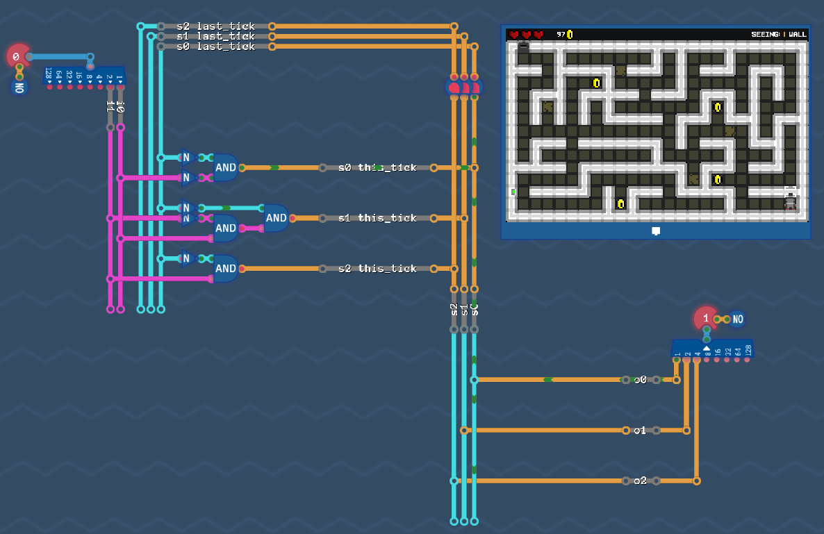
Last, but not least: we have to add our output circuit.
Note: We have to decide if we want to react on our new values immediately, or one tick later (like in saving gracefully). We basically have to decide if we want to pick up the s-Values before the delay line, or after it. Of course our robot has to act in the same tick, as he sees a wall or an opening - so we need to pick up the signals from our current tick (before the delay line).
Just copy paste the output circuit that we build before:
Thats it - thats all we need. Go an try it - the robot can now solve the maze!
Now the question is: Where can we get better?
Let's Get Better
Its time for optimizing our state machine!
Note: All the things we do here are dependend on the particular state machine that you have in front of you. There a general things that you can look at, but this time, there is no "Step1/Step2/Step3-Guide" to get to the best solution. So don't be discouraged if you have an "How should i see that?!"-moment. This all comes down to practice and getting a feeling for the things you have to look out for.
Optimizing 1: State Numbers

Remember when i stopped you from optimizing redundant wires? Of course you can do that, but if you really want to improve the circuit, we have to start somewhere else: with the numbering of the states.
The number that we assign to each individual state is completely up to us. We can choose whatever we want as long as each state number is unique. This is where we can improve.
Lets take a look at the graph that we had after Step 2: Add Outputs before we assigned any numbers to the states. Do you see that the output values themselfes already produce unique numbers?
Thats great, because that means, if we assign these numbers to their states, then the state variables are equal to the output signals and we don't need any logic to translate state signals to output signals - only straight wires from our s-wires to the output!
Note: The fact that our output signals are unique in each state is a special case! If you come across a state machine where multiple states have the same output, then you still have to give them a unique idea - but it's a good idea to keep the numbers as close to your output signals as possible.
So what does this look like?
Now our outputs are equal to our s-wires. The output circuit therefore looks like this:
Of corse this comes at the cost of adding a new state variable that we didn't need before, but maybe thats not so bad. We have to rewire our s-circuit anyways, so lets do that and apply more optimizations there.
Optimizing 2: Simplify Your S-circuit
We changed our state codes so now we have to change our s-circuit as well, so that it matches the graph again. Lets do the same as we did in Step 6: Build the transition circuit.
For each bit in our state code, we look at all the states where it is , and "collect" all the arrows (transitions) that led to that state.
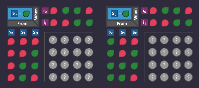
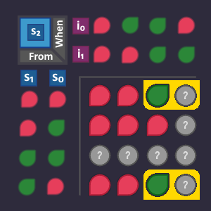
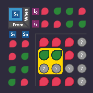
But this time, we organise the signals for the arrows in a KV diagram. An arrow is defined by the state in which it emerges (3 bits for the origin state) and by the conditions that are assigned to it (2 bits because each condition is represented by 2 bits). So we need a KV diagram with 3+2=5 variables to represent each possible arrow. A 5-bit KV diagramm consists of two 4-bit KV maps in which the missing 5th bit is considered in the first map, and considered in the second map.
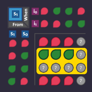
The raw KV diagram looks like this and it has a place for each possible arrow in the graph. These are not two different KV diagrams! They belong together so that we have a spot for each possible combination.
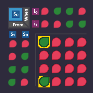
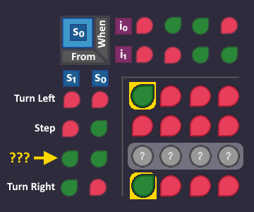
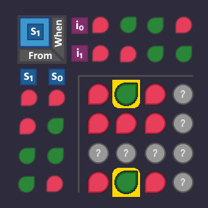
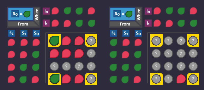
Lets begin with our circuit to create the signal . Look at all arrows that lead to a state where it is .
Now we take all these arrows (where they are comming from, and under what condition) and set it to in our KV diagram, because that are exactly the conditions in which our should turn . All other positions are .
The two arrows produce 2 bits in our KV diagram, that are right next to each other - creating a 2-bit block. This means that we need 1 bit fewer to describe that block than if we were to describe each arrow individually.
The table that describes this block looks like this (we don't need ):
And when we build that, it would lead to the following s-circuit:
We could now go ahead and do the same with the two other bits as well, BUT we stop right here, because there are more things that we can do to get even better...
Optimizing 3: Things That Can Never Happen

When we filled out our KV diagram for , we turned all the bits that corresponded to an arrow to and left every other bit at .
But there are some combinations that can never ever happen!
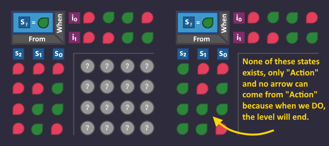
For example:
There is no way that an arrow can start from a state where = .
Why? Because when s2 is , the only existing state is , which is "Action". In that state, we are about to open the door and the level is over! We can not use another arrow from that state.
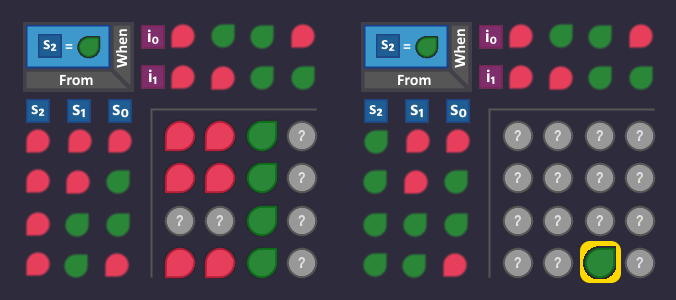
That means, we can ignore the whole second KV map and also in all other KV diagrams
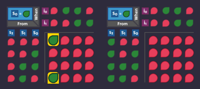
Knowing that, our KV diagram for turns into this:
So we got rid of the gate - yay! But there is more
Let's take another look at our state machine:
We can ignore and see that there is no state, where is . But in our KV diagram, there is a whole row for potential arrows, comming out of , which can never happen (because there is no state for it).
So let's overwrite that row with a "don't care" signal, that we can use to build bigger blocks:
>> "Waaait! You said we get bigger blocks, this doesn't help to get bigger blocks! SCAM!" <<
Yes, yes - but keep in mind that this also applies for our other 2 bits and , that we haven't looked at, yet. And also, we are still not done...
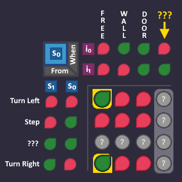
Let's revisit the inputs, that our robot can have:
Nothing and Coin is the same for us (= "Free"), so we can ignore i3 and i2 - so far so good. But if you look closely, you can see that the input combination = also never happens!
This is a whole column in our KV diagram, that we can ignore! More don't care signals for us!
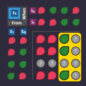
Do you see the 4-bit block, that we can build now?
This block is described by the following table:
So we cut off yet another gate - nice!
Optimizing 3.5: Interim Result
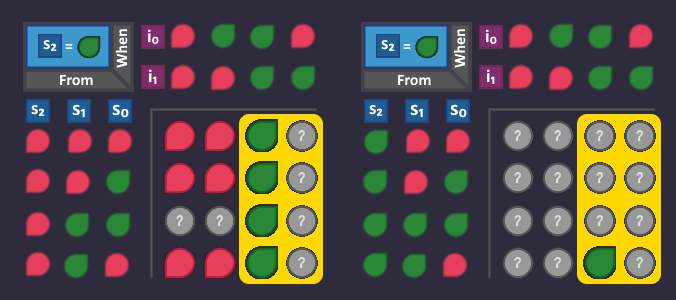
It's getting better and better! And i think it's time, that we apply our optimization to our other 2 missing state bits and .
Alright - time for ! What are the conditions, to turn that bit to ? Let's see...
All yellow arrows go directly in our modified KV diagram
Which leads to the following table
Expanding our circuit...
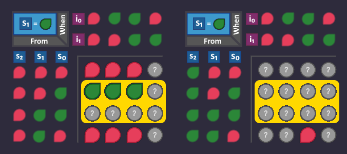
And finally the same again for
Collecting all the arrows again and building blocks:
Leading to a table...
Which again expands our circuit:
Thats our complete s-circuit for all 3 bits.
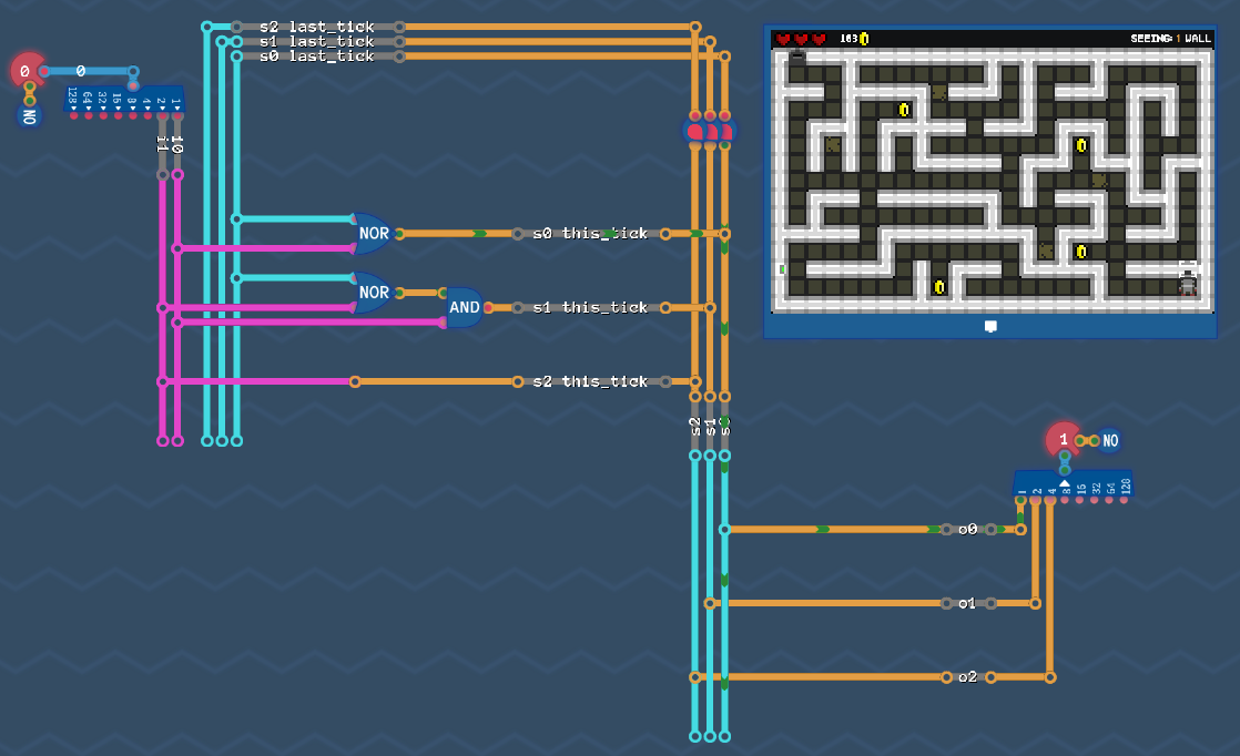
So just for fun - let's wire that up with our output circuit and see if it still solves our maze:
Spoiler: It does :)
Do you think it's time to finally optimize some gates using de'morgans law? Nope! There is still more fancy stuff that we can do!
Optimizing 4: Things That Are Allowed To Happen
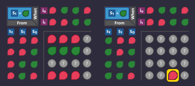
We have 3 KV diagrams now, one for each s-Bit. Each bit in one of these diagrams represents an arrow in our graph. All bits represent arrows, that are either not visible or leading to a state, where its corresponding s-Bit is .
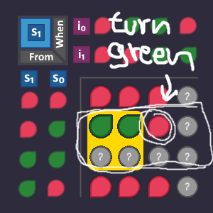
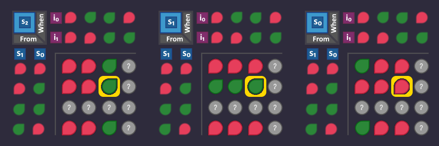
Let's take a look at our three KV diagrams. Note that in each one of them, there is a bit, which, if turned into , would allow us to build bigger blocks.
Suppose that this bit was , what would that mean? It means that there is an arrow in our picture, starting from state (Step) and when the condition (Free) is active, it would lead to a state, where is - so before the change we landed in , and now we turn s0 on, and we would land in (Step) again.
So this is the arrow, that we would create, and we now have to interpret, if that is ok for us.
So is it ok to add this arrow?
Answer: NO! That would totally ruin our robot behaviour, because when we are in state Step, we would take another step if we see nothing and probably pass the door and/or miss intersections.
So we can not turn that bit to to get bigger blocks :(
Maybe on , let's see...
Which arrow does that bit describe?
We start at Step again, and when we see a Wall, we usually would go to (Turn left), but this time we turn on, so we land in (Turn Right).
So is it ok to add this arrow?
Answer: Again NO! The first thing that we have to do after we take a step, is to check our left hand side, or we won't reach the end. So again nothing to get us bigger blocks :(
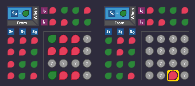
But have still one bit left, let's check out
So again: Which arrow is that?
We start in Step yet again, but this time we see a Door. Usually, we would go to (Turn left), but this time, the arrow turns the bit on. So we land in (Action).
Sounds promising! Let's take a look at the state machine:
YES! That could work! Assume that we just stepped forward and see a door, then it's totally fine to go to the Action state and open it, finishing the level.
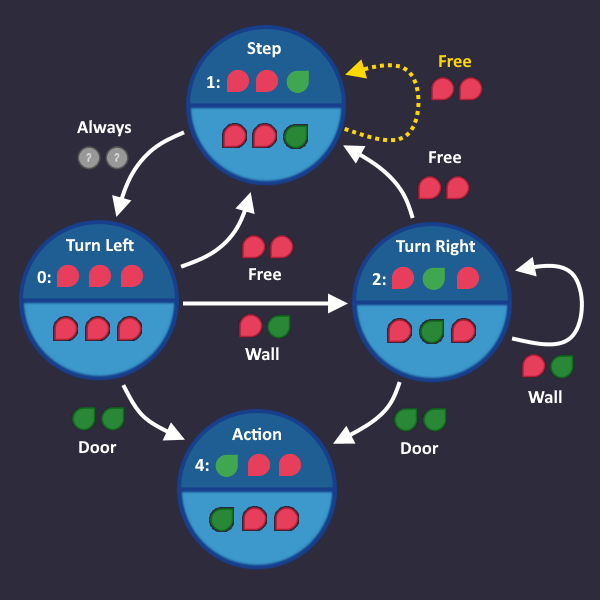
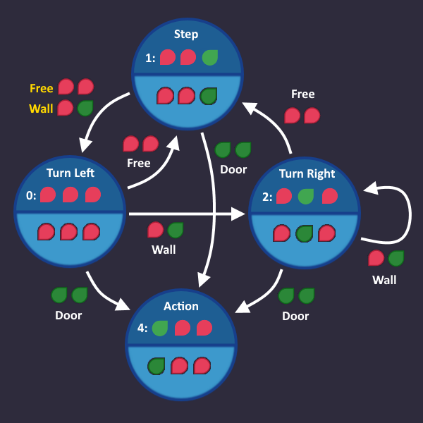
But there is one last thing that we have to take care of, before we can add that arrow: We have to adjust the conditions of the other arrows, because before our change, that condition was part of the "Always" arrow! Taking it away from there also changes the s-circuits for all bits, what would be turned , using the "Always" arrow. If it had been in their KC diagrams, it would be now, because we took it away. Luckily "Always" leads to , so there is no s-Bit that is affected by our change. But nevertheless, we have to "cut out" the "Door"-condition from the "Always" arrow. We do that by listing all conditions except "Door" (which is only Wall and Free).
So a quick adjustment and our state machine looks like this:
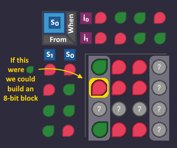
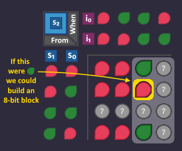
With this change, the intresting bit, that we had in our KV diagram turns and we can build an 8-bit block:
Which leads us to an even smaller table:
So our optimized s-circuit for looks like this:
Slow but steady we are reaching a point where we can't get any better.
Optimizing 5: De'Morgan And Boolean Laws
It's time to polish our circuit by doing some boolean algebra. We don't do any high level tricky stuff here - just the application of a few rules, so that we can get rid of the NOT gates in our circuit.
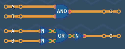
De'Morgans LawDe'Morgans law says, that we can turn an AND into an OR, by surrounding it with NOTs and vice versa.
So these two circuits behave exactly the same
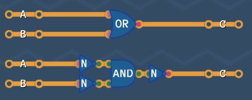
And so do these
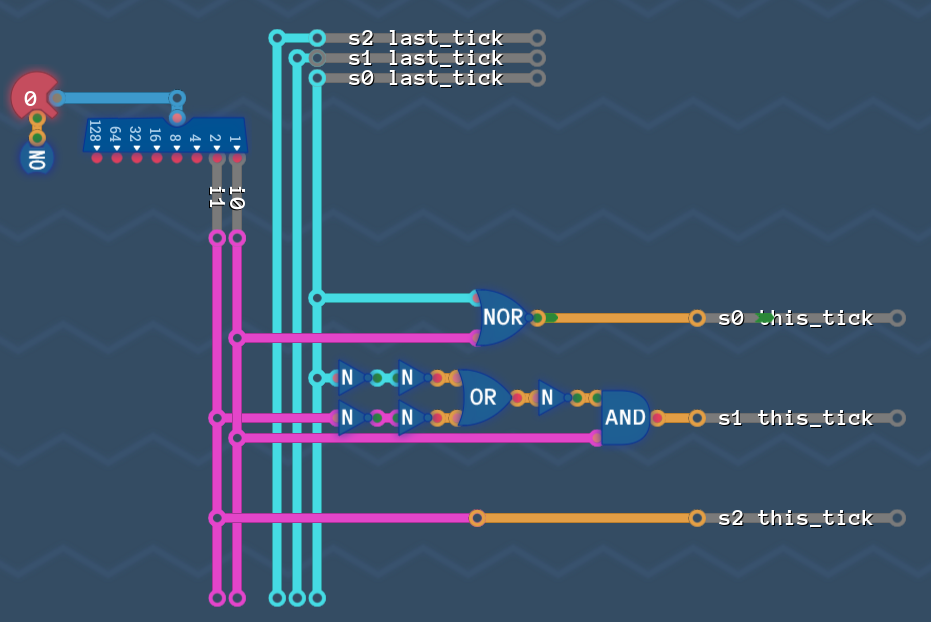
Our circuit looks almost like a de'morgen circuit:
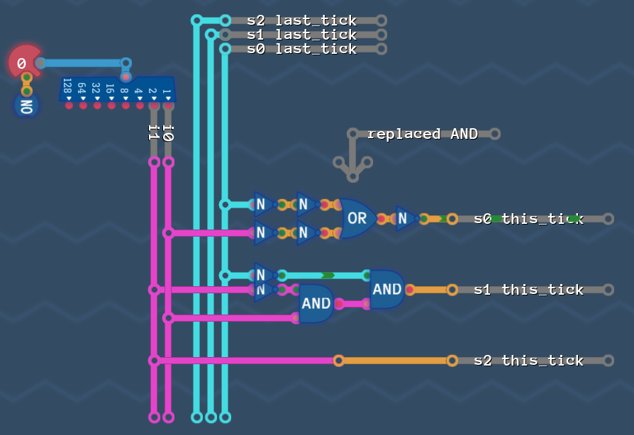
So here is what we do: we take the AND there and replace it with an OR as in De'Morgans law.
Now the double NOTs cancel out, and the remaining OR , followed by a NOT turns into a NOR:
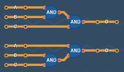
Boolean lawsThere are more laws around to simplify circuits, <here is the wikipedia page>[en.wikipedia.org] , if you want a full list (De'morgans laws are in there as well), but the one we need to simplify our circuit is the "Associativity of AND". Which means, that if you have and AND with more that 2 inputs, then it doesn't matter in which order you AND first.
So these two circuits are the same:
Let's apply that to our circuit, because there, we have 2 ANDs chained up. The idea is, to plug both NOT-inputs into the same AND, so that we can apply De'Morgan again.
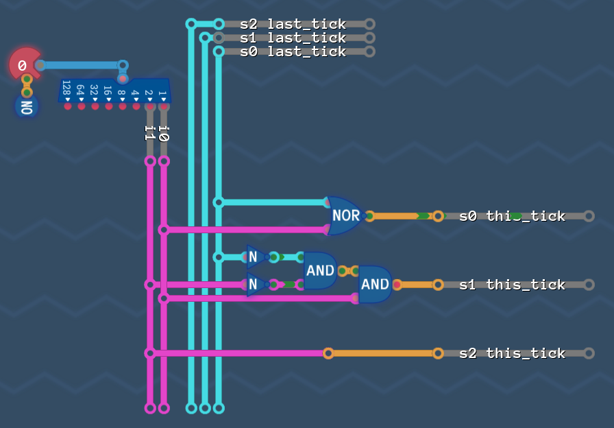
With the now reordered AND, we can do the same as we did with s0: De'Morgan the AND into an OR:
And finally the NOTs cancel out again and the OR followed by a NOT turns into a NOR:
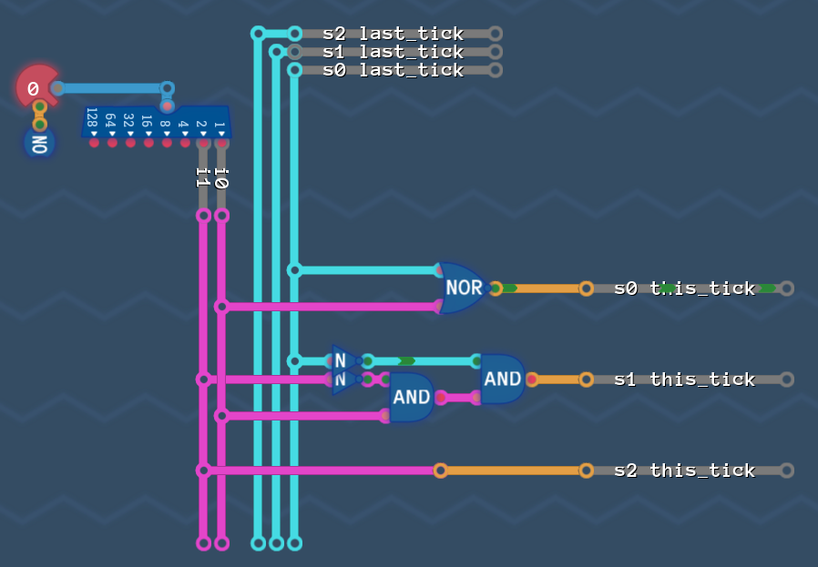
Put everything together and remove dead wires
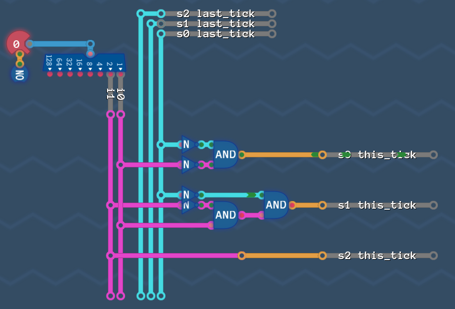
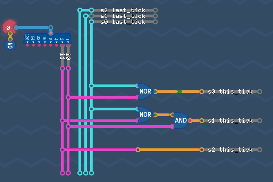
So let's put everything back together:
Looks good, but the wires "s2 last_tick" and "s1 last_tick" are not connected to anything! So we can just delete them and get rid of the delay line.
And this is it! That's our state machine that can't get any better, with a score of 4/4!
How cool is that :D
This is the end.
<roll credits>
... or is it?!
Optimizing 6: A Different Solution
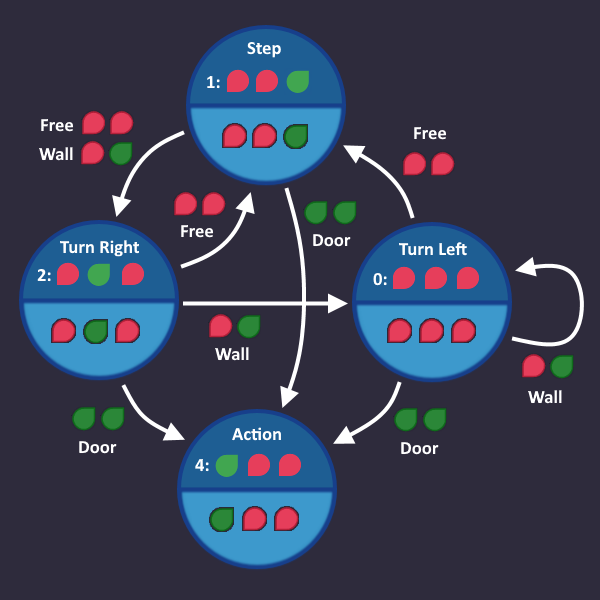
There is no way we can get any better for our solution to the algorithm. But let's go all the way back and read the level description again. Maybe there IS a way to get better.
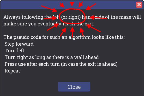
Here is the description again, and i have subtly highlighted the hint for you:
>> You are kidding right?! How's that gonna change anything - it's just mirrored! I don't wanna do everything again :( <<
Luckily we don't have to. We take all the good ideas from before - modify our state machine a little bit, and see how the s-circuits change.
So where did we leave off last time with our state machine?
So let's swap Turn left and Turn right. So our robot watches to its right first, then turn left to look for an opening. Everything else stayes the same.
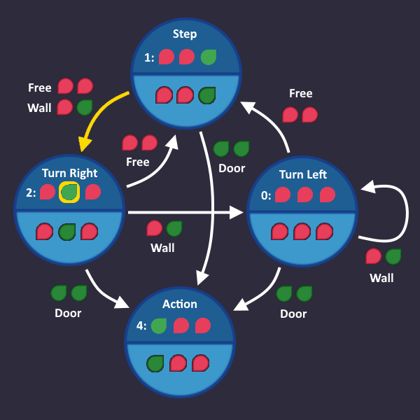
Time to collect arrows again, starting with
The KV diagram for stays the same, which makes sense, because the left and right state both fed into Step with , so by just flipping them, nothing happens.
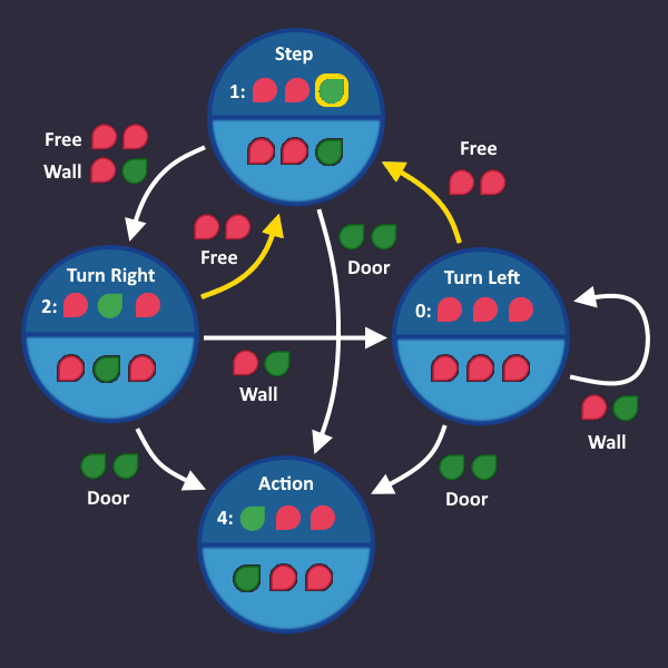
Let's go on with
Notice that the arrow, that goes into Turn Right, has 2 conditions - we put both in our diagram
And for
With this KV diagram (again, the same that we had last time, because the conditions stayed the same)
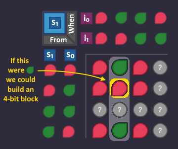
So the only real difference is in in , where we moved from a 2-bit block to a 4-bit block. It's something, i guess - let's build it:
Because and have the same KV diagram as before, we only have to modify our circuit, which cuts off a NOR, but we still need the NOT. This time however, we can't get rid of the NOT :( De'Morgan is only usefull when both inputs have a NOT - not just one. And that means, that this is sill a 4/4 solution, like the one we had before.
>> WAAIT!! I FOUND IT!!! GO BACK TO THE S1 DIAGRAM! <<
Okay?! Nice - what did you find? Show me
>> HAH! I learned something in "Optimizing 4: Things that are allowed to happen"! We can turn that bit to green without breaking our robot and get a 8 bit block <<
>> Turning that bit to green means, that we go to "Turn left" when we see a door, which is allowed. Thats how it's described in the algorithm anyways. And i tested it - and it works! <<
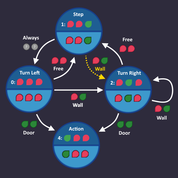
Good idea - but how does your state machine looks like now, when you add that arrow?
>> Uhm... the bit says that we come from "Step" under the condition "Door"... so like this: <<
So far so good, but have you also thought about the fact, that the "door" arrow already points to "Action"? And when you take it away from "Action" - it turns its bit to in the "Action" KV diagram? We would lose the 8-bit block there.
>> But it works! <<
Yes - you found the right solution! But it doesn't work for the reason you think it does. The circuit you build no longer matches our state machine, and we have to explain, why it still works. (And hope that in the future no self-destruction action is implemented on output ...
>> What??? <<
We have to figure out why that works. Let me explain...
Optimizing 7: Try Ideas - But Do It Properly
Let's look at the state machine that you came up with and its KV diagrams
(I have separated the door arrow from the other two conditions)
Nice blocks there - the circuit would definitely be better than ours!
But now you have a contradition in your machine. What is the machine supposed to do, when it sees a door? Go to "Action" and open the door, or go to "Turn right"?
Here is the thing: Contradictions are only a thing in our graph. There is no contradiction in the circuit - every step is perfectly described by the equations (and KV diagrams) that we build. The question is: what does the circuit do in this situation? Which state does it prefer?
The state that we land in is determined by the 3 s-Variables for our next state. So lets see what happens for when we are in "Step" and see "Door":
This is what each s-Bit would do. We would land in state , which does not exists! At least not in our graph... yet.
You know what? Let's go on and see what happens in that state. So instead of two contradicting arrows, what really happens is that we go in a new mysterious state .
Okay we may have opened pandoras box here...
Remember when we build our KV diagrams and said "We can ignore s2, because there is no state where an arrow can come out of a state where s2 ="?
Well, now we have such a state.
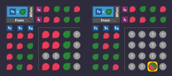
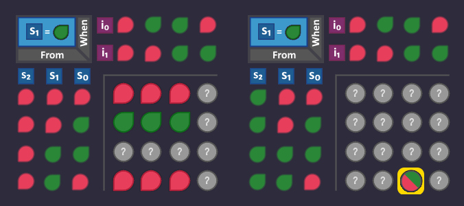
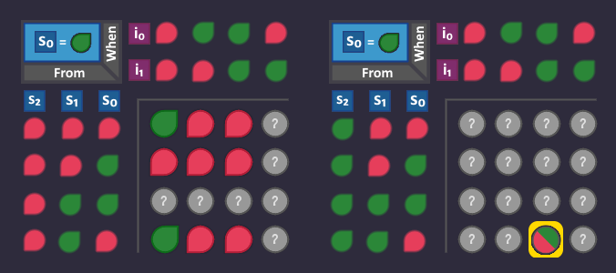
That means our 3 KV diagrams become three-dimensional again, with a second half where is .
But bfore we adjust our KV diagrams, let's quickly analyze what can happen when we are in the Mystery state.
The output, that we send to the robot is = 6, which does not exist (would be a pity if this was the self-destruct command). So the robot does nothing. But that also means, that the input signals doesn't change! Hence, we can only see "Door" and nothing else - everything else turns into "don't care" in out KV diagrams, since it can never happen!
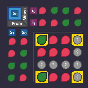
Let's apply these findings to our KV diagrams. The only thing we know is, that the combination "Mystery" with condition "Door" is no longer "don't care". Very other bit in the second KV map is still "don't care" because they can never happen.
What we DON'T know is the value of these bits, so let's put a placeholder there.
The value of these bits is determined by our s-circuit = our blocks that we built from the KV diagrams. If a bit is in a block, it turns , if it is not in a block it turns . So let's take the same blocks that we had before and put it back in, because we want to see what the circuit does, without us changing anything (the blocks now extend over both maps combined). This turns our placeholders into fix values, depending on whether they are in a block or not.
Now the bits are fixed, and we see which state is going to be active, when we come from "Mystery" and see a door:
We would land in = = Action!
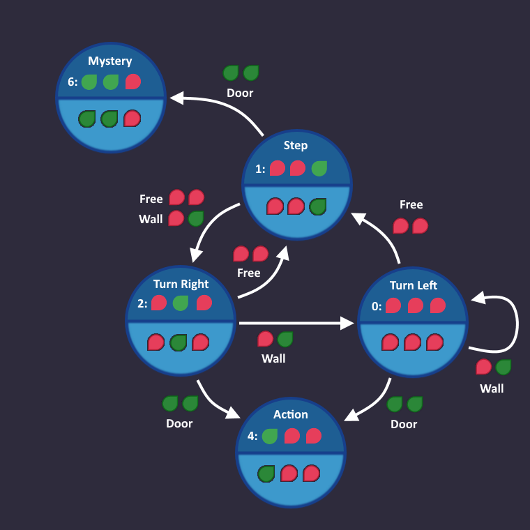
So our final state machine, that is actually underlying our KV blocks is this:
When the robot is in "Step" sees a door, we output first (which fortunately doesn't break anything), and then go to "Action" and open the door. It works!
Now we just have to finish it!
The End
So this is our final state machine
Which is described by these KV diagrams:
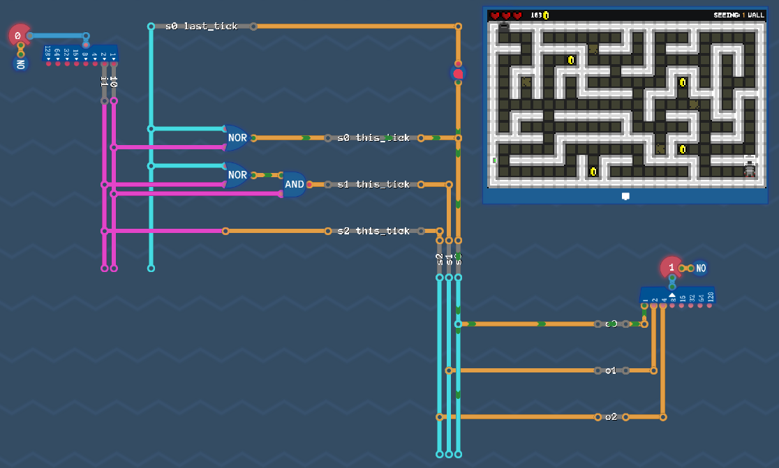
The only thing left for us to do is to build the circuits described by the tables (+ De'Morgan).
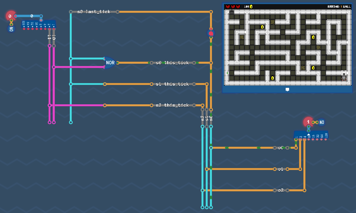
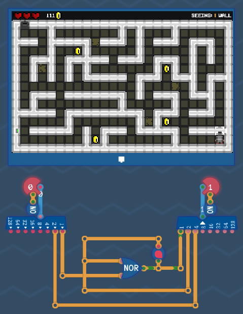
Or, if you clean it up a little bit:
Result: To solve the maze - you need only 2 gates (one of which is a delay line).
<Roll credits... again>
A few final notes:
You may have noticed that the end of chapter "Optimization 6" and the whole chapter of "Optimization 7" was just an expansion of chapter "Optimizing 4: Things that are allowed to happen" with its only purpose of "Is that bit-change ok for us?". So keep in mind that this is not always an easy question to answer.
However, i was very surprised abount the amount of stuff and things that happen in this level. My original goal was to go all the way down to the 4/4 solution (end of Chapter "Optimizing 5") and leave the 2/2 solution to the reader as an exercise. Well... by doing this "exercise" myself, i simply had to explain it in detail, because this contradiction, that we had with the two door signals is easy to ignore when it solves the level. In reality however, you have to be really careful with that, because this hidden mystery state (that you encounter when you leave the contradiction in place) can trigger something completely unexpected.
Hope that gives you a glimpse on how state machines work. There is a lot more to state machines than presented here. Especially when you want to use this concept in real life, you have to deal with signal syncronisation, stability of states and so on.
Feel free to leave a comment and tell me if there are parts, where my explanation isn't detailed enough, or things that i rushed over, but actually need more pictures etc. Also spelling and grammar mistakes please :)
Well - that's it! Thanks for reading!
Source: https://steamcommunity.com/sharedfiles/filedetails/?id=2842294429
More Turing Complete guilds
- All Guilds
- Turing Complete Guide 202
- Turing Complete: Basic Logic-Manual
- Robot Racing
- Turing Complete: Basic Logic-Solution
- Turing Complete: CPU Architecture-Solution
- Turing Complete: Arithmetic and Memory-Solution
- The 6502 Microprocessor
- Turing Complete: All-level walkthrough
- Turing Complete Guide 157
- / Turing Complete