
Quick Notes
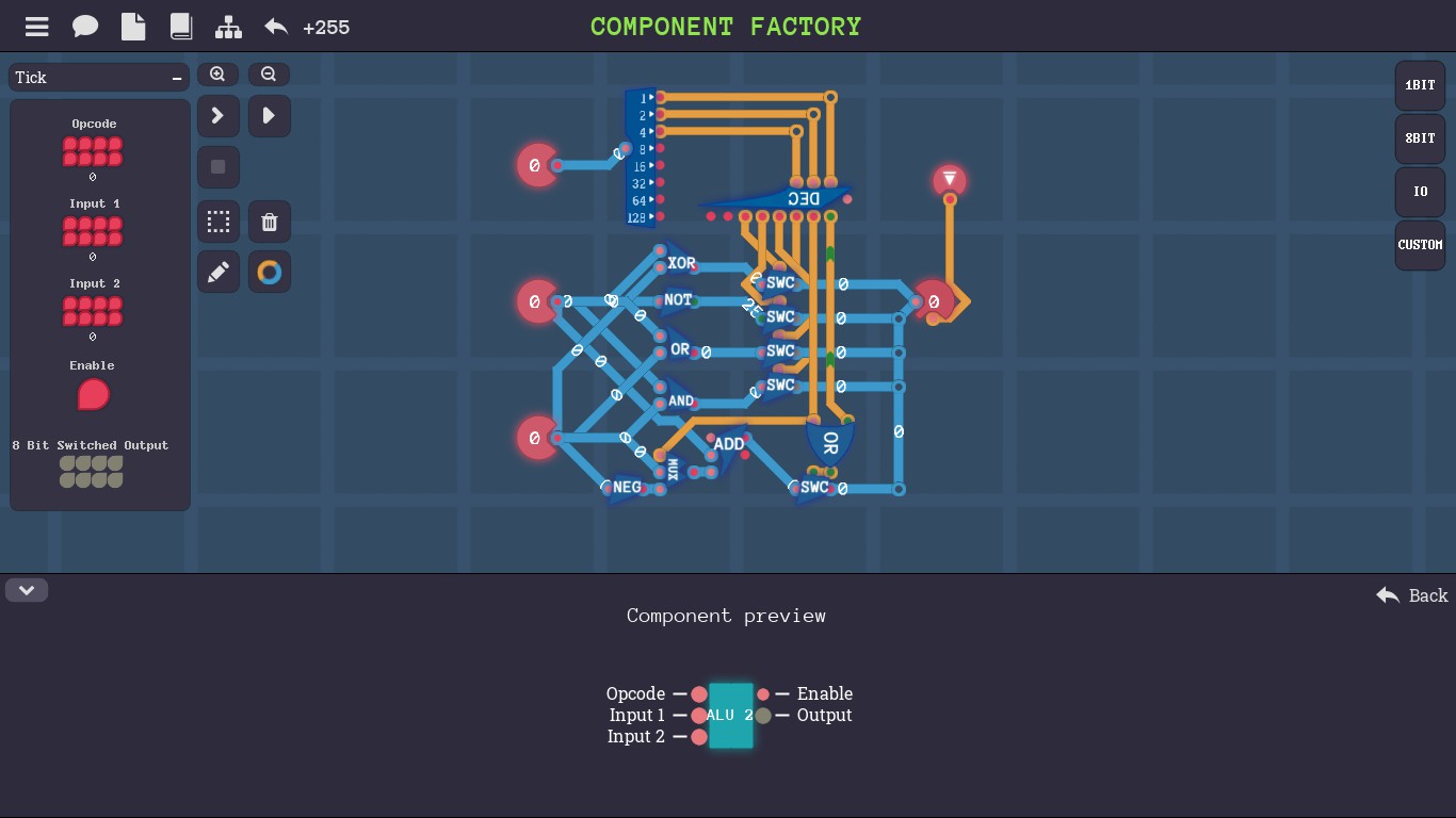
Component Factory The player can customize components in the component factory. The circuit defines the behavior of the component and th layout defines the shape of the component.
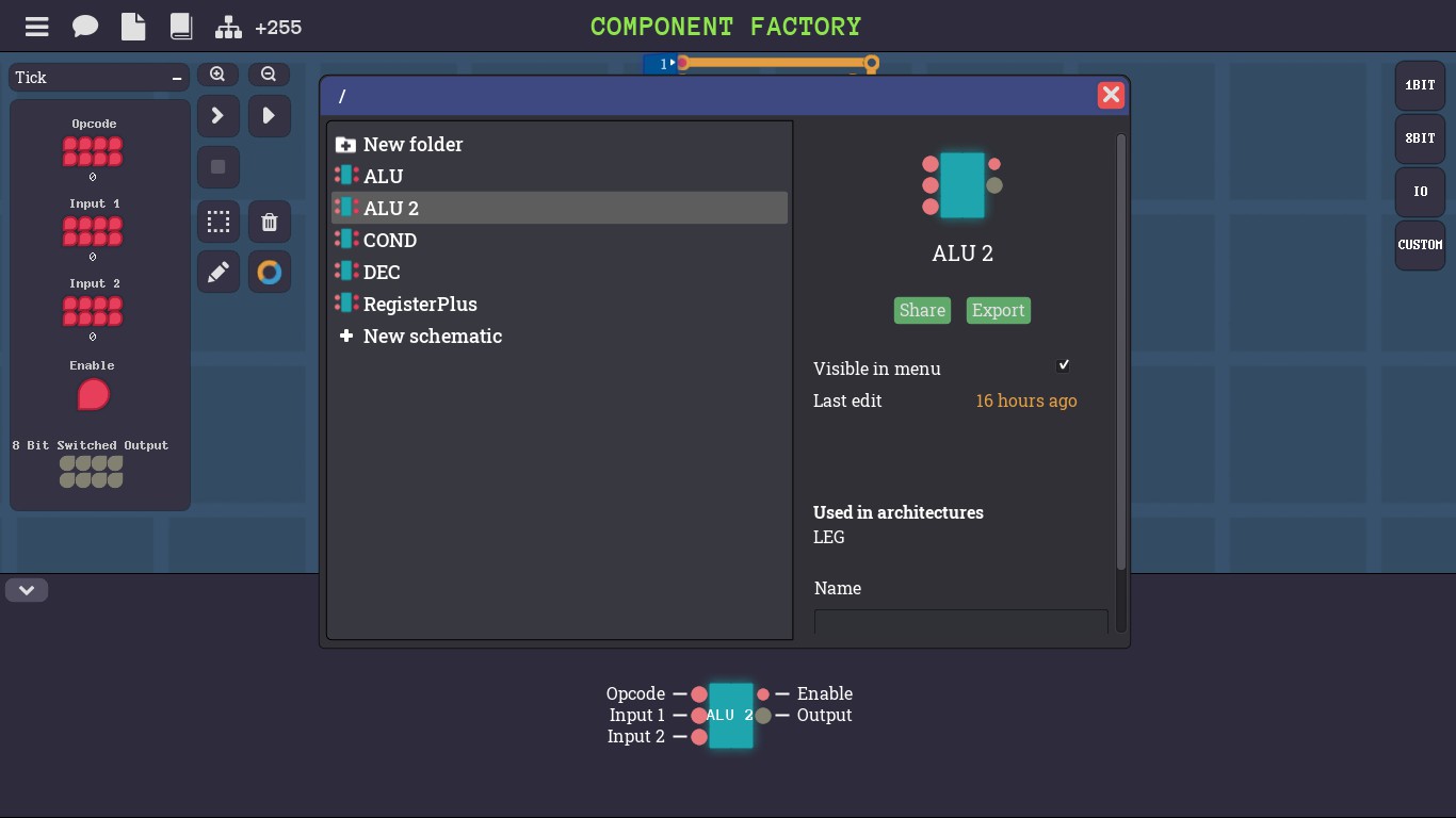
To build a customized component, click the "wrench" icon in any level to go to the component factory. Then click the third "paper" icon to open the schematic folder. In the folder, the player can manage the schematics of customized components. All customized components can be used to create larger components or architecture.
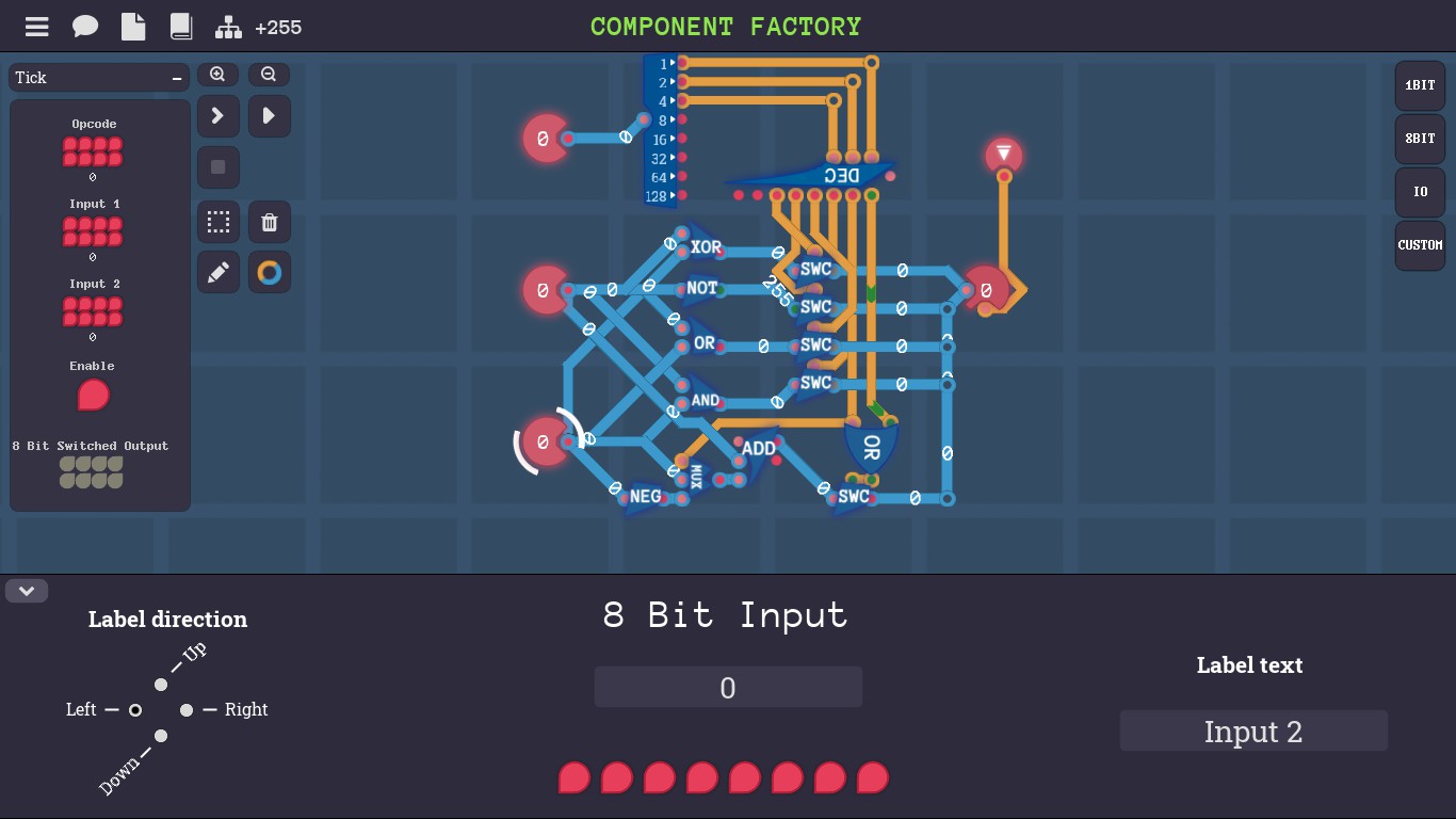
Input, output and components are required for a customized component. The player can label each input or output by clicking the input or output the player wants to label. The player can put the label in "label text" and adjust the direction by clicking the corresponding dot on the left section "label direction".
ConditionsConditions are expressions assigned to a truth value. If the condition is true, then the output signal is on, otherwise the output signal is off. When we compare real numbers, "less than" <, "equal to" = and "greater than" > are common conditions.
Useful PropertiesIf x,y,a are real numbers, then
Ifx<yx=yx>yAll ax+a<y+ax+a=y+ax+a>y+aa<0ax>ayax=ayax<aya=0ax=ay=0ax=ay=0ax=ay=0a>0ax<ayax=ayax>ay
CPU Architecture
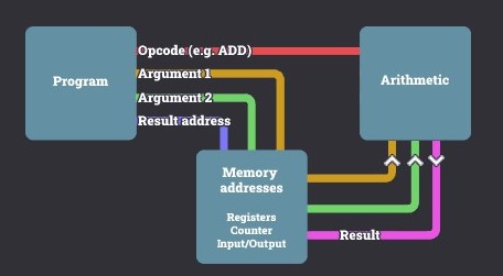
A CPU architecture contains three parts: data, operation and instruction.
Data is usually saved to or loaded from memory units such as registers and RAM. Each memory unit has a unique address code able to identify which data should be used in a computation.
An operation is a function that takes inputs (arguments) to a unique output (result) such as addition and multiplication. Both inputs and output come from data memory. Each operation has a unique code able to identify which operation should be performed in a computation.
Instruction is a code that indicates which data should be used and which operation should be performed in a computation. A program is a chronological sequence of instructions. A counter is used to address the instruction performing in a program.
Links
https://steamcommunity.com/sharedfiles/filedetails/?id=3058316651
Arithmetic Engine
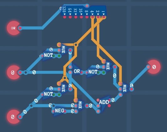
Based on the layout in the level "Logic Engine", use an adder, a negator and two selectors to create a circuit for addition and subtraction. Bit 2 determines the logic mode (OR, NAND, NOR, AND) or arithmetic mode (ADD, SUB). In the arithmetic mode, bit 0 determines ADD or SUB.
Conditions
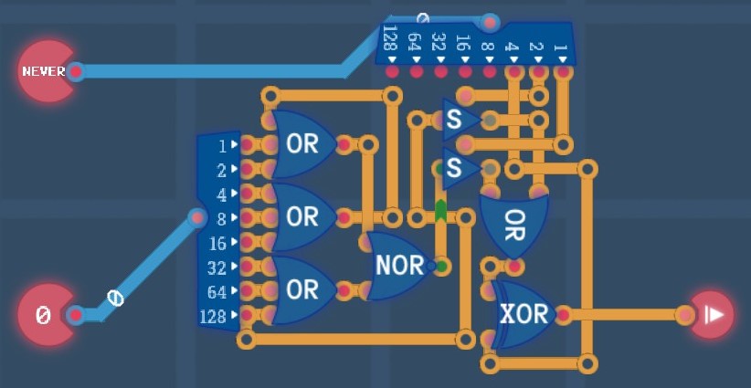
If a signed number is negative (less than 0), the highest bit is 1. If the number is 0, all its bits are 0.
Therefore we need a splitter to split the value byte. We don't need any extra component to create the condition signal "<0" because the signal of the highest bit is on the splitter. To create the condition "=0", we are based on the logical expression:
[A_0][A_1]...[A_7] (all bits are 0)
[A_0+A_1+...+A_7] (De Morgan's law)
[(A_0+A_1+(A_2+A_3+A_4))+(A_5+A_6+A_7)] (Associativity)
NOR(OR(A_0,A_1,OR(A_2,A_3,A_4)),OR(A_5,A_6,A_7))So we need three 3-input OR gates and a NOR gate to follow the expression.
The first bit of the instruction byte turns on the condition signal "=0". The second bit turns on the condition signal "<0". So we need a splitter to split the instruction byte, two 1-bit switches to control the condition signals and an OR gate to merge the two condition signals. Finally, the third bit inverts the merged condition signal, so we need an XOR gate.
Registers
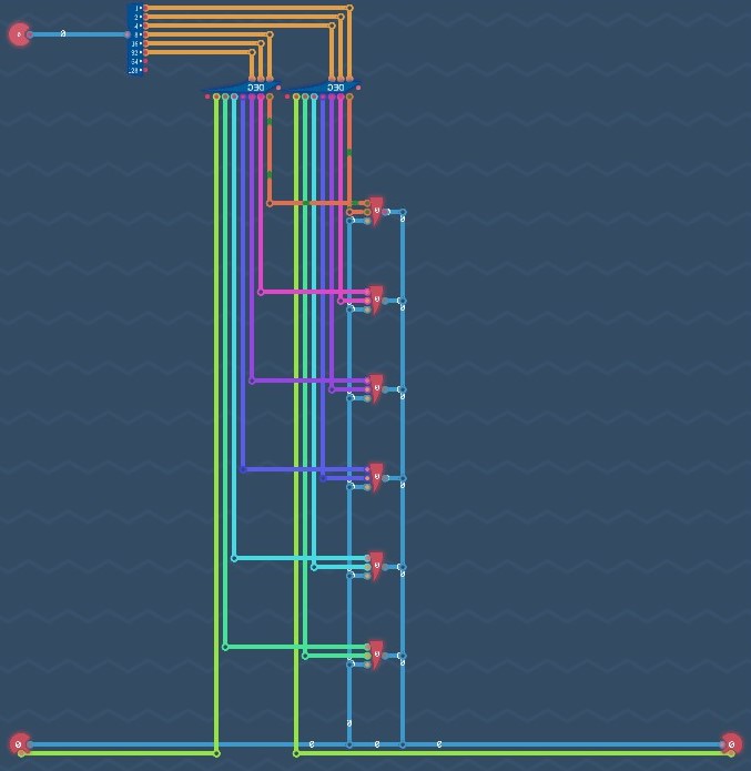
Bit 0 to 2 determine which register or output receives the data. Bit 3 to 5 determine which register or input sends the data. So we need two 3-bit decoders to decode each group of three bits. When a register receives the data, the data is saved to the register. When a register sends the data, the data is loaded from the register. Finally, we need to create the bus that wires up each register, input and output.
Instruction Decoder

Decode the highest two bits of the input value and send each code (0 to 3) to the correct output.
Calculations
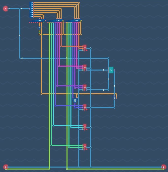
When the copy mode is on, the first six bits determine the source and destination. When the copy mode is off, the two decoders that create the source or destination signals should be disabled. When the calculation mode is on, the first three bits determine the operation, register 1 and 2 become the first and second input, and the output is saved to register 3. When the calculation mode is off, the bus should not carry the output from the ALU.
Program
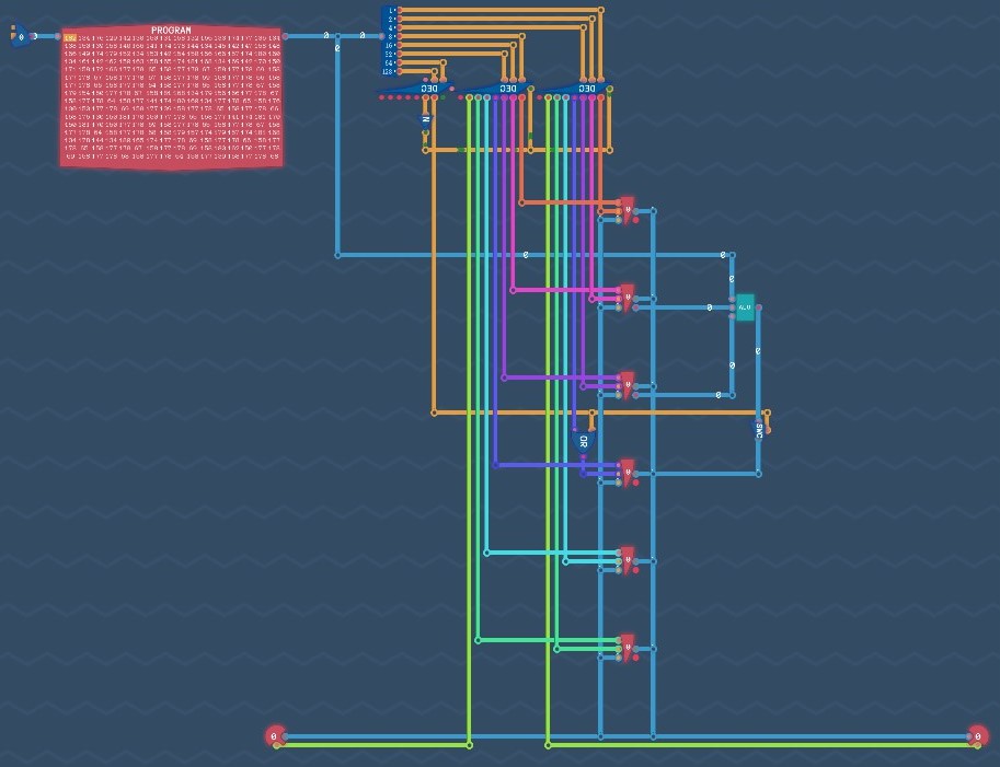
Replace the input with the program panel and attach a counter to the address port. The number in the counter is increased by 1 and the next instruction code in the program is performed after each tick.
Immediate Values
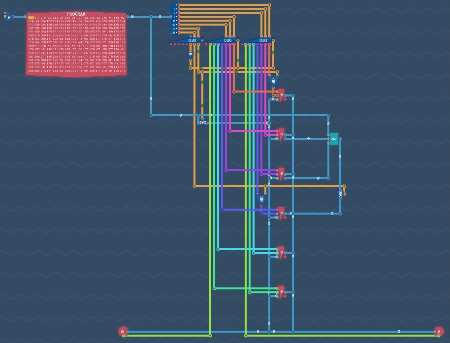
When the immediate value mode is on, the instruction code from the program is directly saved to register 0.
Turing Complete
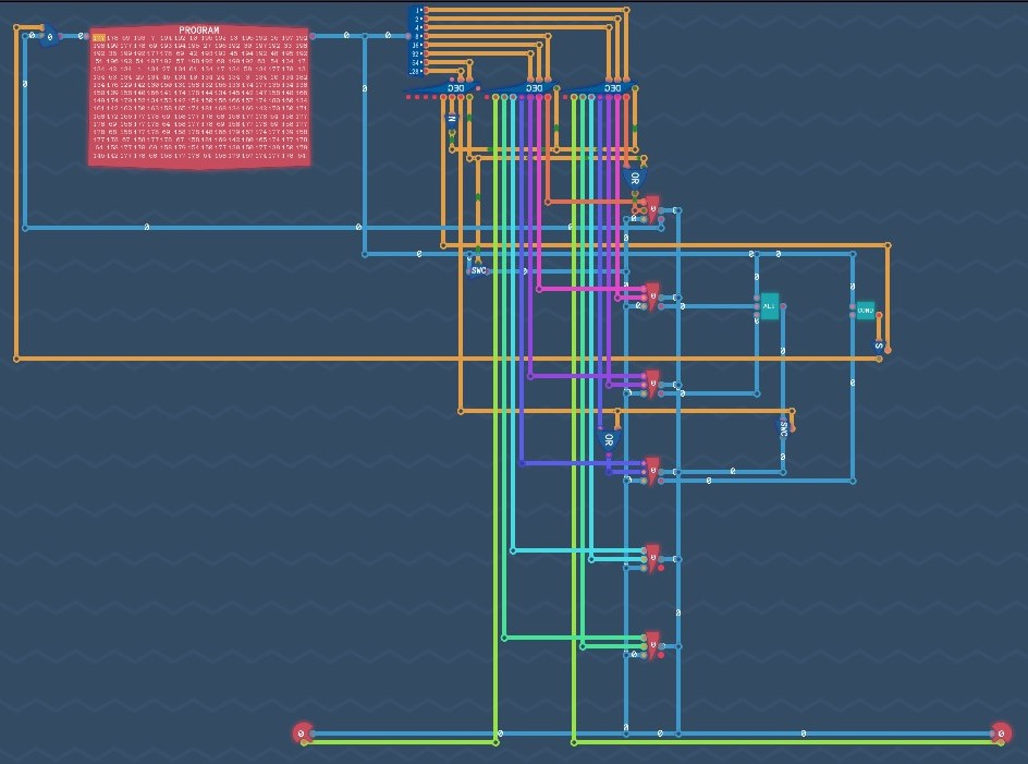
When the condition mode is on, the value in register 3 is used to determine if the condition is true. If the condition is true, the value in the counter is replaced by the value in register 0.
Source: https://steamcommunity.com/sharedfiles/filedetails/?id=3089627419
More Turing Complete guilds
- All Guilds
- Turing Complete Guide 202
- Turing Complete: Basic Logic-Manual
- Robot Racing
- Turing Complete: Basic Logic-Solution
- Turing Complete: Arithmetic and Memory-Solution
- The 6502 Microprocessor
- Turing Complete: All-level walkthrough
- Turing Complete Guide 157
- / Turing Complete