
Quick Notes
Binary NumbersBinary numbers are numbers whose digits represent powers of 2 in the form:
S(a_i*2^i, i=0,n-1)where S is the iterated sum of terms a_i*2^i from i=0 to i=n-1, a_i is the (i+1)-th bit (binary digit) that is either 0 or 1 and n is the number of bits. For example, the decimal number 6 can be written as
0*2^0+1*2^1+1*2^2Hence we have a_0=0, a_1=1, a_2=1 and n=3. 6 in base 2 is 110, which has three bits.
Addition and Multiplication Table+010011110
*01000101
Two's ComplementTwo's complement is a common way to represent negative binary numbers by inverting all bits and then add 1 (except for the number -2^(n-1)). For any signed n-bit number, the highest bit represents -2^(n-1) instead of 2^(n-1).
For example, the signed binary number 1011 represents
1*2^0+1*2^1+0*2^2-1*2^3=1+2-8=-5. Its two's complement is 0100+1=0101, which represents
1*2^0+0*2^1+1*2^2-0*2^3=1+4=5.
Counting PrinciplesCounting principles are the methods used to find the number of all possible ways to perform tasks, indivisible processes that cannot go with another process at the same time.
Addition PrincipleSuppose we begin to perform one of the tasks t_1, t_2, ..., t_n. For 1 ≤ i ≤ n, there are m_i ways to perform the task t_i. Therefore the number of all possible ways is
N=m_1+m_2+...+m_nFor example, imagine we are going to eat either pizza or sushi at a restaurant. If the restaurant only offers 2 kinds of pizza and 3 kinds of sushi, then we have 2+3=5 options.
Pizza 1
Pizza 2
Sushi 1
Sushi 2
Sushi 3Multiplication PrincipleNow we begin to perform the tasks t_1, t_2, ..., t_n step by step in order. In this case, the number of all possible ways is
N=m_1*m_2*...*m_nNow imagine we are going to eat pizza first and sushi after we finish pizza at the same restaurant. In this case, we have 2*3=6 options.
Pizza 1, Sushi 1
Pizza 1, Sushi 2
Pizza 1, Sushi 3
Pizza 2, Sushi 1
Pizza 2, Sushi 2
Pizza 2, Sushi 3
Permutations and CombinationsPermutations are arrangements of distinct elements in order. The equation for the (partial) permutation of k elements from n elements is
P(n,k)=n!/(n-k)!=n*(n-1)*...*(n-k+1)where n!=n*(n-1)*...*2*1 is called n factorial and 0!=1. When k=n, we have the equation for the (total) permutation of n elements:
P(n)=n!Combinations are sets of distinct elements regardless of the order of selections. The equation for the combination of k elements from n elements is
C(n,k)=P(n,k)/P(k)=n!/(k!*(n-k)!)For example, if n=3 and k=2. then
P(3,2)=3!/(3-2)!=3*2=6
C(3,2)=P(3,2)/P(2)=6/2!=3Therefore, we can see that
Permutations: (1,2), (1,3), (2,1), (2,3), (3,1), (3,2)
Combinations: {1,2}, {1,3}, {2,3}
Links
https://steamcommunity.com/sharedfiles/filedetails/?id=3058316651
Circular Dependency

A circular dependency is the case where there is a loop (closed path) in a circuit such that the input of a component depends on its output, so we can build a loop passing through at least two components.
Delayed Lines

A delay can postpone a signal for one tick, so we can connect them in series for many ticks.
Odd Ticks

A NOT gate can invert a signal, and a delay can hold its input for one tick. We can see the oscillation of the signal if we make a simple loop passing through an inverter and a delay.
Bit Inverter

A{+}0=A and A{+}1=[A]
Odd Number Of Signals

1{+}1=0 and A{+}0=A, so any pair of 1s becomes 0 and each 0 can be eliminated in a direct sum. We can see the direct sum is 1 if there is an odd number of 1s.
Double Trouble
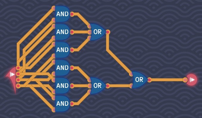
If we let the number of signals be not less than 2, then we need to make sure the circuit can judge if there are at least two signals. Since conjunction is commutative, there are C(4,2)=4!/(2!*2!)=24/(2*2)=6 possibilities.
Counting Signals
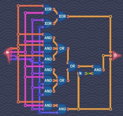
We have the number of signals ranging from 0 to 4. If the number is 4, only the 4's bit is on. If the number is odd (1 and 3), the 1's bit is on. If the number is not less than 2 but less than 4 (2 and 3), the 2's bit is on. So we need to create the circuits:
In the level "odd number of signals";
In the level "double trouble";
An AND gate with four inputs giving the condition "=4";
A NOT gate and AND gate combining the conditions "≠4" and "≥2".
Double The Number

2 is 10 in base-2. Like a factor of ten in base-10, doubling a number in base-2 is simply shifting all bits of that number to one higher bit.
Half Adder
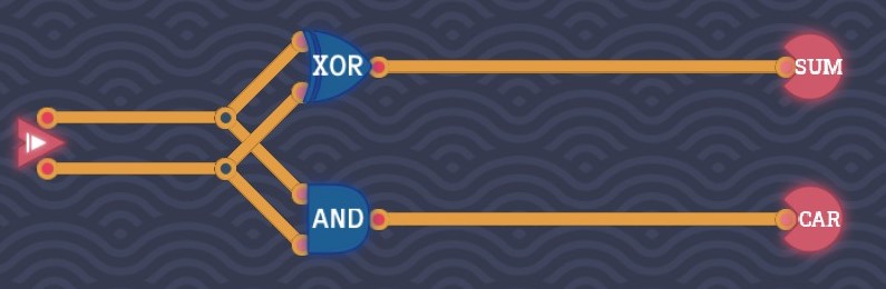
The sum of two 1-bit numbers yields a number that has two bits at most. That extra digit is called a carry. From the truth table
ABCS0000010110011110we can see that
S=A{+}B
C=AB
Full Adder
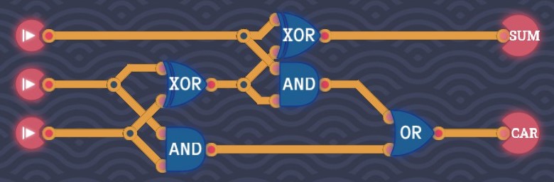
We can use a half adder to add two 1-bit numbers. Adding three 1-bit numbers can be divided into two steps:
Add any two 1-bit numbers;
Add the last 1-bit number to that sum. As a result, we have the truth table:
ABC_inC_outS0000001001100011101000101011101011011111We can see that
S=A{+}B{+}C_in
C_out=AB+C_in(A{+}B)
Bit Switch

A bit switch acts like an AND gate, the only difference between a bit switch and an AND gate is no signal is emitted when the switch is off (output is grey instead of pink). That is (N means no signal)
SwitchInputOutput00N01N100111
Byte OR
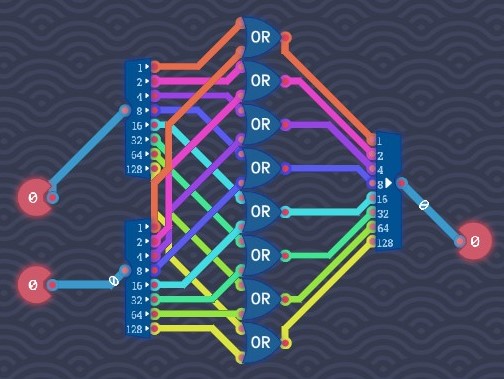
Find the disjunction of each pair of two bits with the same value (power of 2).
Byte NOT

Find the negation of each bit.
Adding Bytes
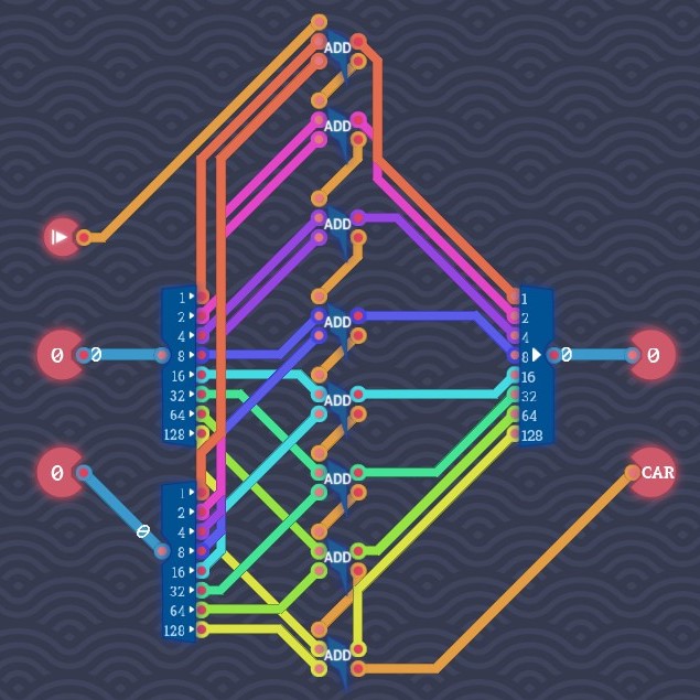
Ripple-Carry Adder Based on the vertical algorithm of addition of two 8-bit numbers A and B,
C_8C_7C_6C_5C_4C_3C_2C_1C_0 0A_7A_6A_5A_4A_3A_2A_1A_0 0B_7B_6B_5B_4B_3B_2B_1B_0 C_8S_7S_6S_5S_4S_3S_2S_1S_0 we can use 8 full adders to add each pair of two bits and the carry from one lower bit. Note that
S_i=A_i{+}B_i{+}C_i
C_(i+1)=A_iB_i+C_i(A_i{+}B_i)
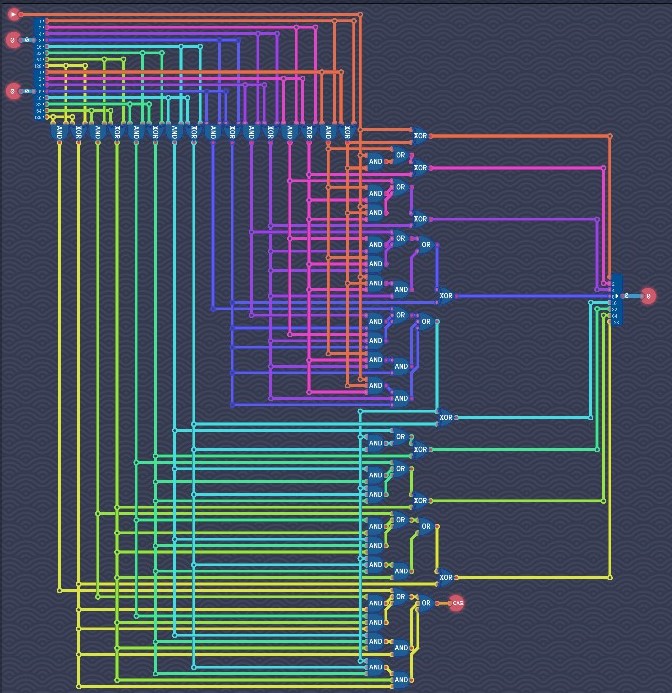
Carry-Lookahead Adder In a ripple-carry adder, a i-th bit full adder has to wait for the carry signal C_i from the previous (i-1)-th bit full adder to finish the computation of S_i and C_(i+1). To reduce the propagation delay, we can find a circuit that can compute every carry without the long signal propagation through the previous adders. In other words, only A_i, B_i and C_0 are used to calculate each C_(i+1).
Note that
S_i=A_i{+}B_i{+}C_i
C_(i+1)=A_iB_i+C_i(A_i{+}B_i)A_iB_i generates the carry C_(i+1) because 1+1=10, so let G_i=A_iB_i. A_i{+}B_i propagates the carry C_i because if there is a carry and a 1 in the sum, the sum can push the carry to the next bit and become 0, so let P_i=A_i{+}B_i. Therefore,
C_(i+1)=G_i+C_iP_iFor 0≤i≤3, we have
C_1=G_0+C_0P_0
C_2=G_1+C_1P_1=G_1+G_0P_1+C_0P_0P_1
C_3=G_2+C_2P_2=G_2+G_1P_2+G_0P_1P_2+C_0P_0P_1P_2
C_4=G_3+C_3P_3=G_3+G_2P_3+G_1P_2P_3+G_0P_1P_2P_3+C_0P_0P_1P_2P_3So we can build a circuit that directly computes C_1, C_2, C_3 and C_4 from A, B and C_0. Similarly,
C_5=G_4+C_4P_4
C_6=G_5+C_5P_5=G_5+G_4P_5+C_4P_4P_5
C_7=G_6+C_6P_6=G_6+G_5P_6+G_4P_5P_6+C_4P_4P_5P_6
C_8=G_7+C_7P_7=G_7+G_6P_7+G_5P_6P_7+G_4P_5P_6P_7+C_4P_4P_5P_6P_7So we can also build a circuit that directly computes C_5, C_6, C_7 and C_8 from A, B and C_4.
Signed Negator

The negative of a signed number is to invert all its bits and then add 1.
Input Selector
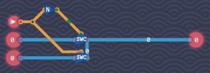
8-bit switches work in the similar way to 1-bit switches do. So we need to turn on the switch of the first input when the switch signal is off and turn on the switch of the second input when the switch signal is on.
The Bus
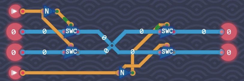
Similar to the level "input selector", we need to build a circuit able to select output based on the output signal. Let the switch of the first output on when the output signal is off and the switch of the second output on when the output signal is on.
Saving Gracefully

When the save signal is off, we need to save the signal that has been already saved in a delay, so we need to create a loop from a delay's output back to its input. When the save signal is on, we need to save the new input value to the delay, so we need to connect the new input to the delay. Use 1-bit switches to control the signal flow.
Saving Bytes
Split a byte and save each bit to a 1-bit memory.
1-Bit Decoder

Turn on the correct output signal for each input signal 0 and 1.
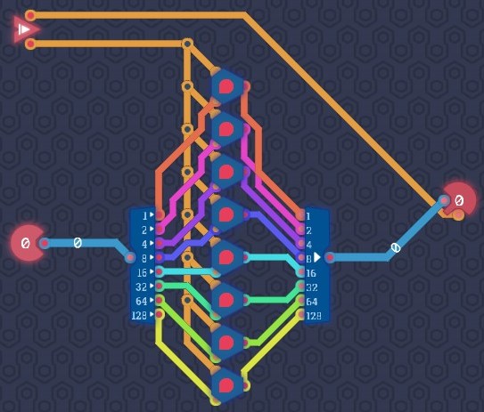
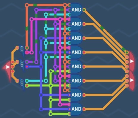
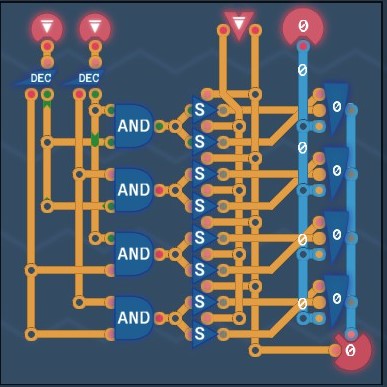
3-Bit Decoder
There are 2^3=8 distinct patterns of a 3-bit code:
000
001
010
011
100
101
110
111Use 8 3-input AND gates to create signals and send them to the right output for each pattern.
Logic Engine
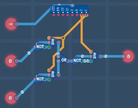
[AB]=[A]+[B]. When the first bit is turned on, two inputs are inverted (OR turned into NAND and NOR turned into AND). When the second bit is turned on, the output is inverted (OR turned into NOR and NAND turned into AND). Therefore we need 3 selectors to control the inversion of input and output signals.
Little Box
There are four distinct register addresses:
A0
A1
B0
B1So we need four registers, four AND gates and eight switches for each register to determine if the load or save mode should be on.
Counter

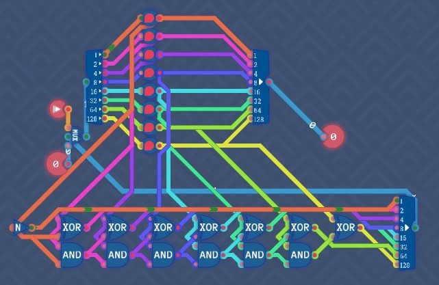
1 should be added to the counter value. In the overwrite mode, the counter should be set to the new input value. No matter which mode the counter is in, the counter should always output its value for every tick. So we need a register to save the counter value, an adder to add 1 to the counter value and a selector to control the signal flow.
Low Gate Score We can simplify both the register and adder part. Since the register always loads its value and save the new value for every tick, the register behaves in the same way as a 8-bit delay (output the value saved from the previous tick and save the input value for the next tick). Therefore 8 1-bit delays are needed to replace the original register.
Since only 1 is added to the counter value, we have
CC_7C_6C_5C_4C_3C_2A_01AA_7A_6A_5A_4A_3A_2A_1A_0B00000000SS_7S_6S_5S_4S_3S_2S_1[A_0]Therefore only half adders are used to add 1 to the counter value. We don't need C_8 from bit 7. Since A{+}1=[A] and A1=A, we only need to send [A_0] to bit 0 and A_0 to the input of the half adder for bit 1 (XOR giving S_1 and AND giving C_2).
Source: https://steamcommunity.com/sharedfiles/filedetails/?id=3078986482
More Turing Complete guilds
- All Guilds
- Turing Complete Guide 202
- Turing Complete: Basic Logic-Manual
- Robot Racing
- Turing Complete: Basic Logic-Solution
- Turing Complete: CPU Architecture-Solution
- The 6502 Microprocessor
- Turing Complete: All-level walkthrough
- Turing Complete Guide 157
- / Turing Complete