
What Are Karnaugh-Veitch Maps?
A Karnaugh-Veitch map is a modified truth table for 4 bytes, which allows to derive simplified circuits for this table just by looking at it. So everytime you come across a logic, that has 3 or 4 bytes of input, you can plug its truth table into a KV map and build the circuit.
Okay, So How Does It Look Like?


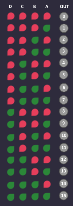

Usually you start with a truth table with 4 inputs and an output column with values that are either or . In this example the output values doesn't matter (yet), but notice that i gave them numbers from 0 to 15 that matches their corresponding input bit pattern.
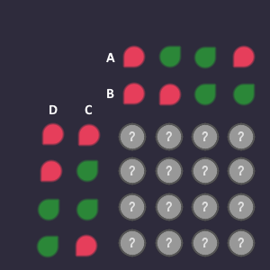
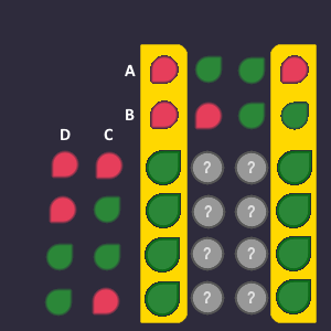
A Karnaugh map is a truth table, where each bit combination is represented in 2D form.
So the outputs are not a straight line like above, but like a square:
⠀
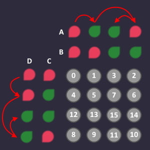
As a careful observer, you may have noticed something strange: The input combinations are not numbered 0-1-2-3 (in binary), but 0-1-3-2!
Originally posted by Whyman:Why though?!
The answer: We make sure, that only 1 bit changes in each step. So if we would go 0-1-2-3, then the step from 1 to 2 in binary would be 01 to 10. Both bits would change, but we only want 1 bit to change at max. This is why we swap the order of the inputs, but make sure, that we still have all possible combinations available.
Originally posted by Whyman:BUT WHYYY?! Yes, yes... later...
Changing the order of the input also changes the order in which we fill in the outputs. Going from left to right, skipping the third column and going from top to bottom, skipping the third row. The white numbers are the order in which you plug in the output values.
How Does This Help Me In Any Way?


BLOCKS!
The anwser is blocks.
Let me explain...
Humans are very good at visual pattern recognition (if the layout favors it). By using the only-1-bit-change trick, we can now combine bits in blocks of size 1,2,3 and 8. When forming blocks, we only focus on the bits! Leaving the bits alone.
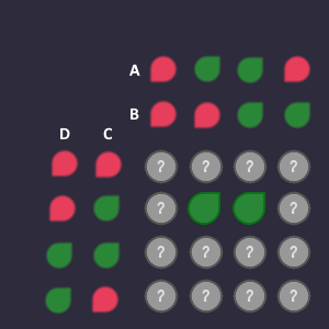
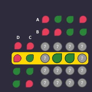
Lets say there are the following 2 green output bits that we are interested in:
Question is: How can we describe these two bits using the bits from the columns and rows?
⠀
Row:
The bits that we are interested in, are in the row where:
Column:
The bits that we are interested in, are in the columns where:
We don't need to describe the two columns, because = already covers both columns.
By putting those together, we can describe the bits as 2-bit block. The bigger the block, the less inputs we need to describe it! So we want to make the blocks as big as possible. To describe a 2-bit block, we need 3 inputs - the 4th does not matter (also a feature of our 1-bit-change-only trick).
The block is described by this combined input conditions:
So now we can AND everything together and the block is done.
Any More Block Limitations?
Only the 1,2,4,8 block size rule.
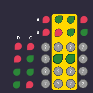
Additional note: The blocks can also go around from left to right, and from top to bottom. So for example, you can do an 8-bit block from left to right (using only one input variable to describe it).
This block is described only by one input variable
Question for you: Can you do a block, that covers only the 4 corners?
So This Is It?
Not quite.
Since we can only do 1,2,4 and 8 bit blocks, we have to combine multiple blocks together, to cover all outputs. Each one of them has to be part of a block. Overlapping blocks are no problem, they are actually quite helpful to create big blocks for missing bits.
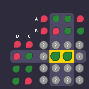
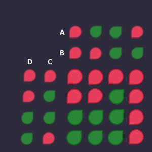
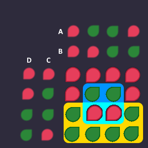
ExampleThis is our truth table, that we already plugged into our Karnaugh map:
Now we have to do blocks of 1,2,4 or 8 (as big as possible) to cover all output bits.
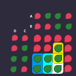
We can do it like this:
We need 3 blocks to cover all bits:
A yellow 2-bit block
A blue 4-bit block
A white 4-bit block
Combined they look like this:
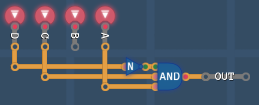
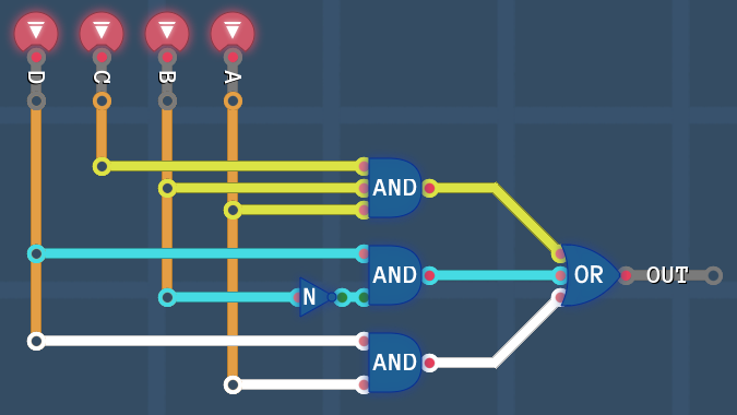
To build the blocks, we AND the inputs and after that we OR the blocks together
And thats it! We created a circuit that describes the truth table completely!
Final Notes
The whole idea is based on the fact that a circuit like this:
(SuperComplexExpression AND a) OR (SuperComplexExpression AND NOT a)
is the same as just
(SuperComplexExpression)
Because it doesn't matter if A is or - either the first part of the bracket is passed through, or the second part. So if only one bit changes, then we can remove that bit from the equation. (I was asked about that fact in my exam, so maybe it is good to know).
You can do a Karnaugh map for 3 bits, by throwing away the two rows on the bottom and the D input.
You can also do a Karnaugh map for 5 bits, by creating two 4-bit maps. One where the 5th bit is and one where the 5th bit is . Then imagine you lay both maps on top of each other, so you can do additional blocks by piercing through both maps.
The way we collected the bits and put together the blocks is called Disjunctive Normal Form (DNF) which focuses on the output bits, which are then ORd together. There is also a Conjunctive Normal Form (CNF) where you focus on the bits and then AND the blocks together (a bit more complicated - you have to look it up).
If you have two potential blocks of bits, but the intersection of those two blocks are , then you can XOR them together instead of OR.
If you have a chess board pattern in your KV map, you can just XOR all inputs together.
Now Its Your Turn!
Here is a task for you:
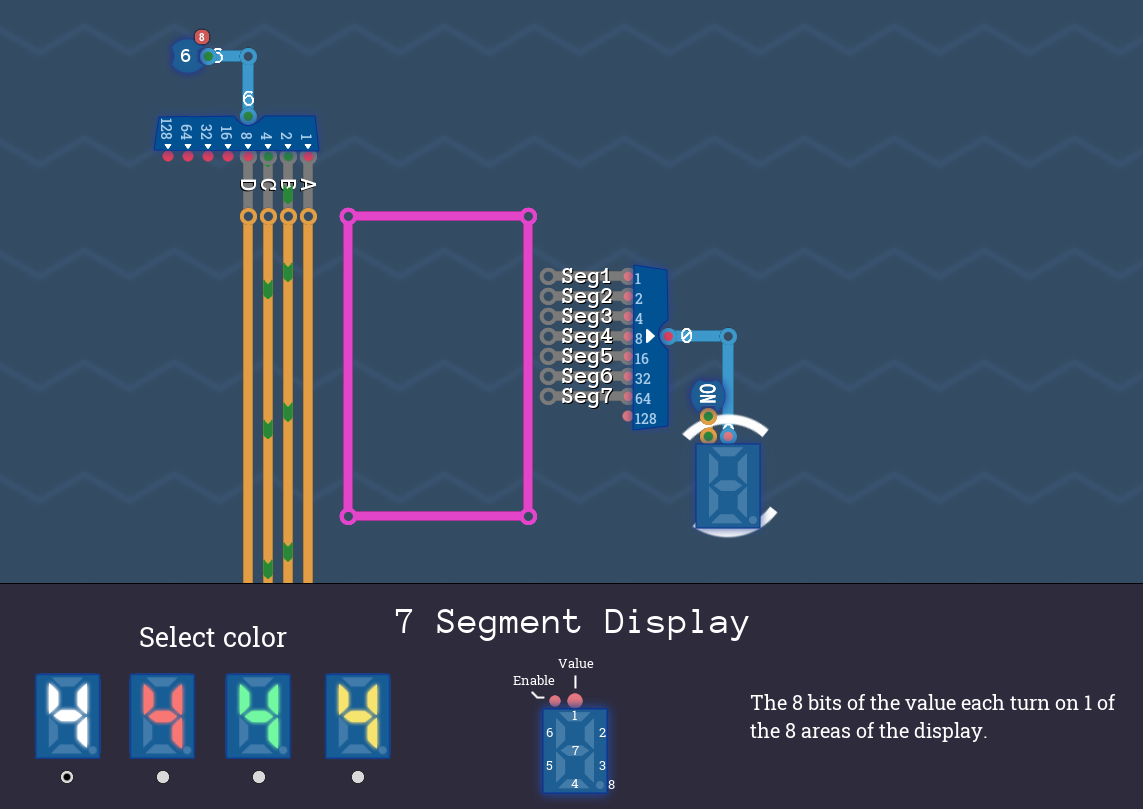
You get a 4 bit number as input, and you have to display the number in decimal. For this purpose there is the 7-Segment display in the sandbox, which has 7 segments that you can turn on and off.
Fill a Karnaugh map for each segment (Seg1 to Seg7) and build a circuit, so that the correct decimal number is displayed for each binary input number. If you want, you can also display 10 as A, 11 as b etc. up to 15 (hex converter). Otherwise the numbers 10-15 do not matter and can be used to build bigger blocks.
In this picture the input number is a binary 6. Build the circuit in the purple box (the box is way to small, i know), so that for the binary 6 the segments 1,6,7,5,4, and 3 are "glowing". (And for the rest of the binary numbers as well from 0 to 9). You need a KV map for each segment. Create the "normal" truth table first, and then fill the map, create blocks and OR them together.
Happy wiring! Hope you learned something :)
Source: https://steamcommunity.com/sharedfiles/filedetails/?id=2828368407
More Turing Complete guilds
- All Guilds
- Turing Complete Guide 202
- Turing Complete: Basic Logic-Manual
- Robot Racing
- Turing Complete: Basic Logic-Solution
- Turing Complete: CPU Architecture-Solution
- Turing Complete: Arithmetic and Memory-Solution
- The 6502 Microprocessor
- Turing Complete: All-level walkthrough
- Turing Complete Guide 157
- / Turing Complete