
Simple guide to backup stationary batteries.
Other Stationeers Guides:- Super Simple Steel Smelting.
- Super Simple Autocycling Airlock.
- Simple Gas Filtration System.
- Simple Logic Chip Solar Tracker.
- Simple Stacker Automatisation.
- Building Your First Base.
- Quick Guide to Auto-Solar Power.
- Guide to Your First Pressurised Base with Airlock.
- Super Simple Base Pressure Regulation.
Overview
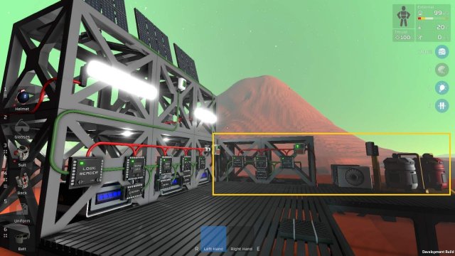
Guide to Stationary Battery Power Backup.
The system shown here was created & tested in Creative mode.
For this guide I created a solar powered stationary(kit) battery charging system, on Mars. 3 solar panels for 3 batteries here, worked OK on Mars during daylight. I included a number of lights , only to create a load on the system, especially at night.
For any reason solar does not put enough charge into the system, a backup was required to maintain the battery array.
Above: Shown here with my solar tracking setup and battery array, using a gas powered generator as backup.
Click on any image for full size view.
"Simplicity is the ultimate sophistication" - Leonardo Da Vinci.
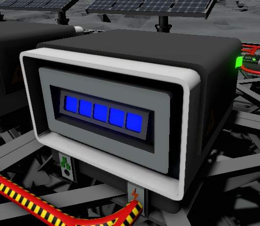
Stationary Batteries
Above: Stationary (Kit) Battery
I have utilised the battery's Mode value for the logic in this system. Mode could be read as 'charge state'. Each battery has 7 modes, indicated by the colour blocks displayed on the front and rear of the unit.
- 0 no blocks
- 1 1 block, red, blinking
- 2 1 block, red
- 3 2 blocks, orange
- 4 3 blocks, yellow
- 5 4 blocks, green
- 6 5 blocks, blue

Hence:
- 0 = not charged/charging
- 6 = fully charged

Front referred to here is the side of the battery having both power and data ports.
Logic
When a battery is less than fully charged, a backup is engaged to bring the battery array to full charge.
- IF battery mode <> 6 THEN
- engage backup charging
- END IF
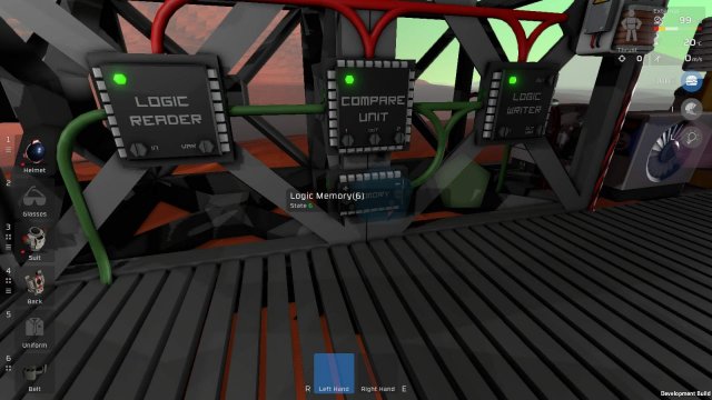
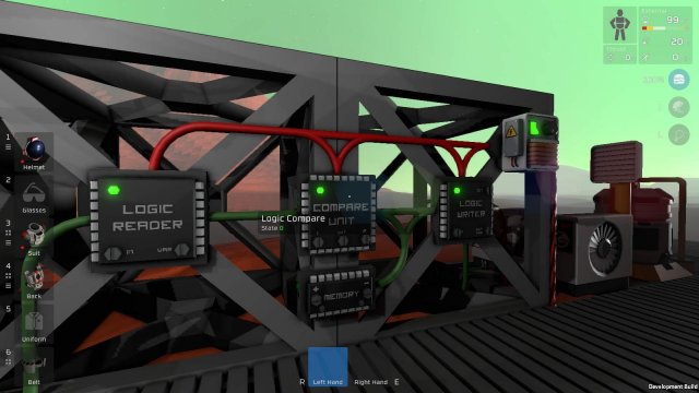
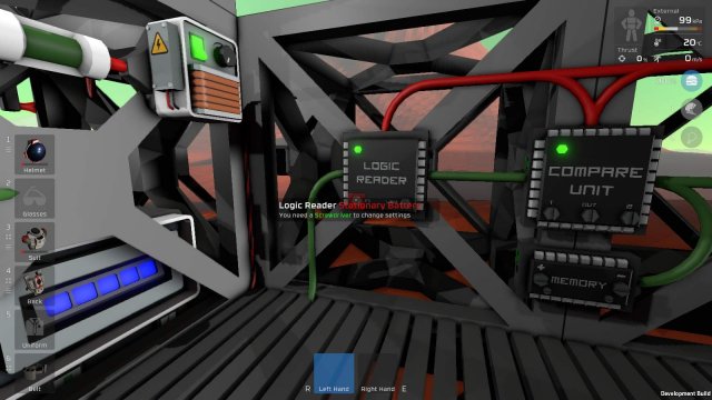
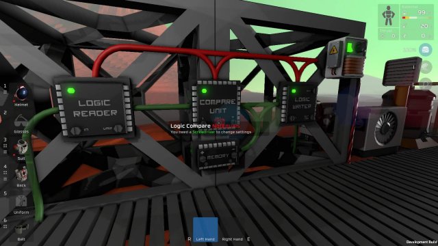
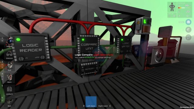
The battery Mode value is read by the Logic Reader from the data port of one of the batteries. The value is passed to the math Compare Unit, to test whether or not it equals 6. The Memory Unit stores this test value 6. The Logic Writer is signalled when the Mode value is not equal to 6. The Logic Writer triggers the ON state of the backup.
The batteries are interconnected as an array. The backup hooks into the solar panel>battery array cable.
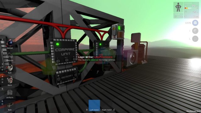
Above: Green cable leads into left data port of the Logic Reader from the data port of one of the batteries.

Detail
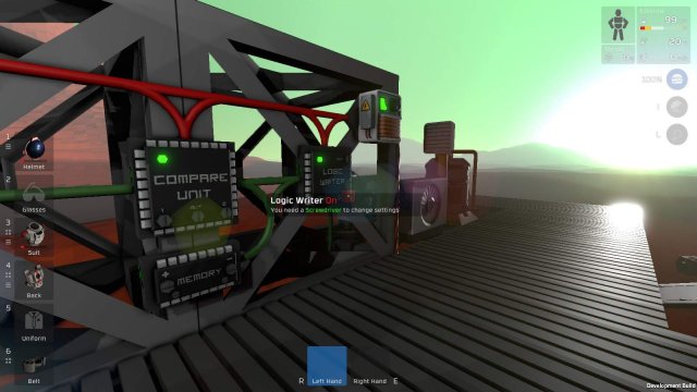
The components and settings are shown in the images below.
Logic Reader: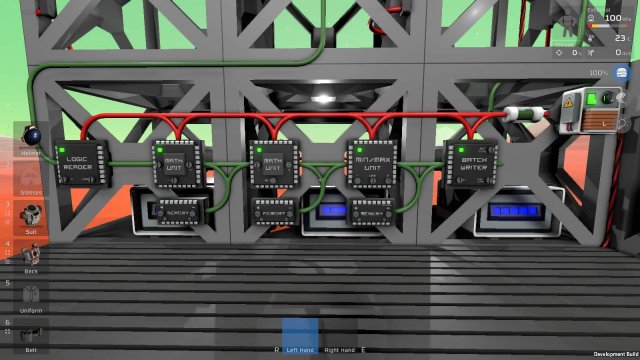
IN = Stationary Battery
VAR= Mode
 Compare Unit:
1 = Logic Reader
OUT = NotEquals
2 = Logic Memory
Memory Unit:Set = 6
Logic Writer:IN = Logic Compare
OUT = Gas Fuel Generator
OUT VAR = ON
Considerations
The system shown here was created & tested in Creative mode. No known reason why it won't 'work' in Survival - the Gas Fuel Generator fuel supply would need to be guaranteed.
The system as shown is powered from the battery array via a small transformer (outputting 100W - sufficient for the logic setup), hence some power remaining in the battery array is required for it to work. Given that it activates when any battery drops off full charge, I don't see this as a problem for my use, however an Area Power Controller (APC) could be used with small battery installed to provide backup power to the logic setup. The presumption being the APC would only be needed when all batteries are dead flat.
The backup charge system may also power anything connected to the batteries, during backup charge.
The amount of load and the time the backup charge system is active, may be affected by anything connected to the batteries during backup charge.
Note the simple data and power cable layout in this guide. It provides me a better idea of data and power flows. In any cabling setup I try not to cramp component layout, but make every effort to create space for a simple and intuitive cabling layout.
Above: The solar tracking logic setup used for this guide. Again note simplicity of cable layout.
Backup System
In this guide you see the Stationary Battery Backup using a Gas Fuel Generator for backup, but any system with an ON/OFF state could be utilised here.
It was tested with an RTG. The RTG does not have an ON/OFF state but a small transformer was installed between the logic setup and the RTG to give the ON/OFF capability.
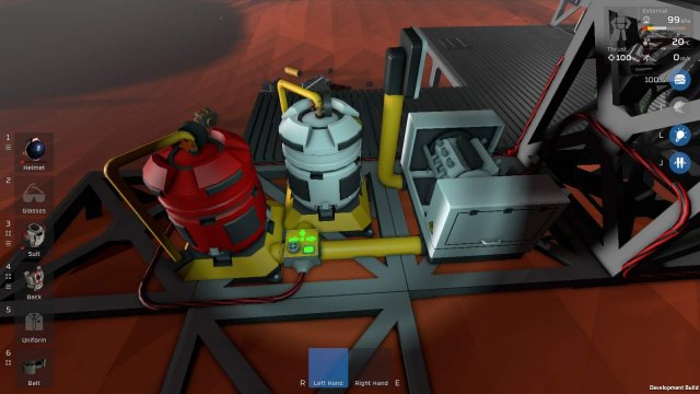
The actual backup system used is not important for the purposes of this guide, but I have included some images of the gas fuel generator system used here, for info.
Above: Gas powered generator as installed.
Green data cable in from Logic Writer. Red heavy cable out, hooks into solar panel>battery array cable
Above: Gas mix & supply
Red heavy cable in from battery array to power gas mixer. Mixes Volatiles (H2) and Oxygen (O2) @ 64/36. Gas waste to atmosphere via passive vent.
Source: https://gameplay.tips/guides/4374-stationeers.html
More Stationeers guilds
- All Guilds
- Stationeers - Simple Stacker Automatisation
- Stationeers - Simple Logic Chip Solar Tracker
- Stationeers - Simple Gas Filtration System
- Stationeers - Vulcan Map Guide
- Stationeers - Super Simple Base Pressure Regulation
- Stationeers - Canister Handling Made Easy
- Stationeers - Easiest Way to Track the Sun
- Stationeers - Logic Thermostat 20-25 C
- Stationeers - Guide to Advanced Furnace Automation
