Definition
timer (n) an automatic mechanism for activating a device at a preset time.
Setup
Wiring
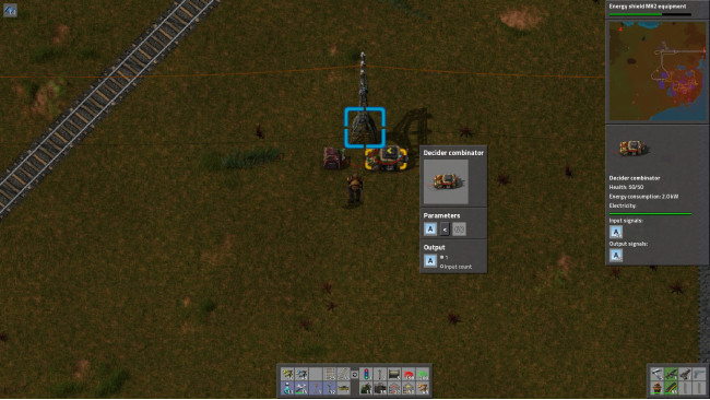
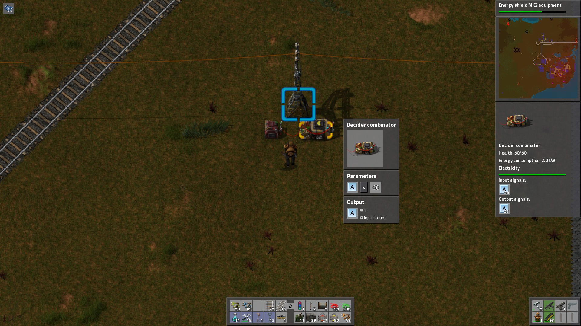
A simple timer is a constant combinator (CC1) connected to a decision combinator (DC1). Wiring is from CC1 to DC1-input, and then from DC1-ouput to DC1-input (back to itself.)
ConfigurationCC1 outputs A=1
DC1 evaluated "A<60", and if true outputs A=(input)
BehaviorTick=0: Initially CC1 outputs A=1
Tick=1: DC1 receives A=1, evalutes A=1, A<60 is true, outputs A=1 (back to itself)
Tick=2: DC1 receives A=1 from CC1 and A=1 from itself, evalutes (inputs are added together) A=2, A<60 is true, outputs A=2 (back to itself)
Tick=3: DC1 receives A=1 from CC1 and A=2 from itself, evaluates (inputs are added together) A=3, A<60 is true, outputs A=3 (back to itself)
.
.
.
Tick=61: DC1 receives A=1 from CC1 and A=60 from itself, evalutaes (inputs are added together) A=3, A<60 is false, outputs nothing (back to itself)
Tick=62: DC1 receives A=1 from CC1 and nothing from itself, evalutes A=1, A<60 is true, outputs A=1 (back to itself)
Loops indefinitely.
Applications
Objective: Frequency control (you want activity A to happen twice as frequently as activity B.)
Configuration:
CC1 outputs A=1;
DC1 accepts input from CC1 and from DC1-output, if A<120 then output A=(input)
DC2 accepts input from DC1, if A=1 then output A=1
DC3 accepts input from DC1, if A=61 then output A=1
L1 (Lamp) accepts red-wire input from DC2 and DC3, with circuit condition A=1
L2 accepts green-wire input from DC3, with circut condition A=1
Results: L1 will flash when Timer is at 1 or 61, but L2 will flash only when Timer is at 61
Objective: Turn on for 60 seconds, then turn off for 60 seconds
Configuration:
CC1 outputs A=1;
DC1 accepts input from CC1 and from DC1-output, if A<7200 (60 seconds * 60 ticks * 2 cycles, on then off.)
DC2 accepts input from DC1, if A<3601 then output A=1
DC3 accepts input from DC1, if A>3600 then output A=1
---
If you're not familiar with SR Latches, please see my tutorial on SR Latches.
---
DC4 accepts input from DC2-red-output and DC5-green-output, if A=0 then output A=1
DC5 accepts input from DC3-red-output and DC4-green-output, if A=0 then output A=1
L1 accepts input from DC5-red-output, with circuit condition A=1
Results: Lamp will turn on for 60 seconds (set condition) and then off for 60 seconds (reset condition).
Final Comments & FAQ
Comments Keep in mind that the larger you combinator network, the more delay there is in each layer of your combinator machine. Each combinator is evaluated every second, but the changes to the circuit network will only be felt after the tick completes.
FAQ
Source: https://steamcommunity.com/sharedfiles/filedetails/?id=686911713
More Factorio guilds
- All Guilds
- Unpatched Bugs List as of Version 1.1.107
- Alternative Atmospherics
- Factorio Guide 842
- Haxard's Blueprint Book v1.1
- Achievements - Saved games
- Factorio
- 22 . Factorio | F
- FACTORIO (UA)
- Factorio Guide 815
- 22 protection options. The best defence in Factorio | F